DiroDi ClassX Assembly Manual
CHAPTER 1: OVERVIEW
HOW TO USE THIS MANUAL
This manual contains several chapters and each chapter contains several steps. Each step has a descriptive paragraph and some photos. By clicking on each photo, you can view it in full size.
This manual explains the assembly instructions mainly. Therefore please also read the other manual that comes with the bike and includes information regarding the operation, maintenance, safety measurements, etc.
IMPORTANT: For the assembly steps, please first completely read a step, view all related photos, and then proceed with performing that step.
If you face any difficulties during the assembly, please contact us via the website’s live chat.
If there are any mistakes in the manual or any information should be added or revised for a better assembly experience, please let us know via our live chat.
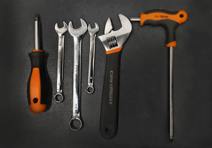
TOOLS REQUIRED
1x Screwdriver
1x 10mm Wrench
1x 15mm Wrench
1x 8mm Wrench
1x Adjustable wrench
1x 5mm Allen key
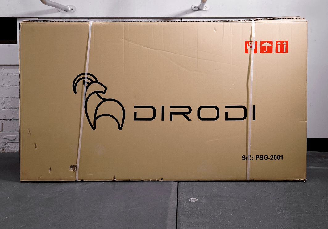
CHAPTER 2: OPENING THE BOX
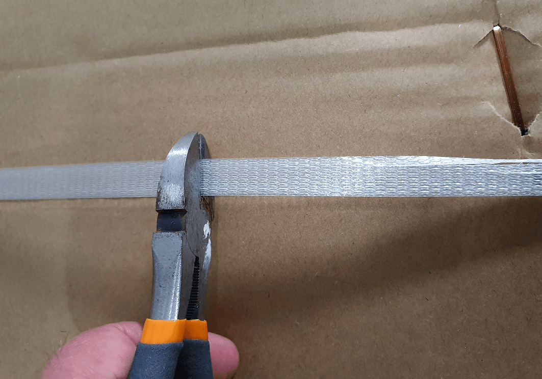
STEP 1
Cut the plastic straps off the bike carton.
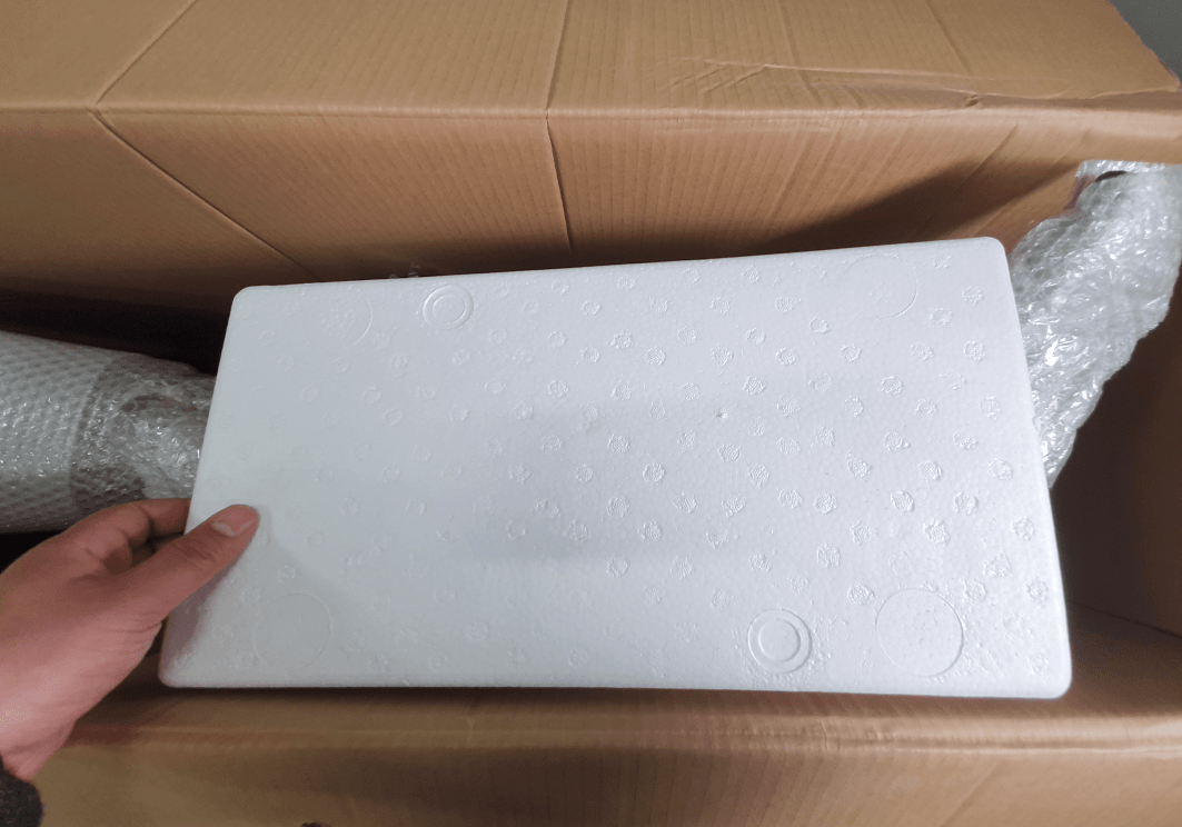
STEP 2
Remove the outer-most protective foams
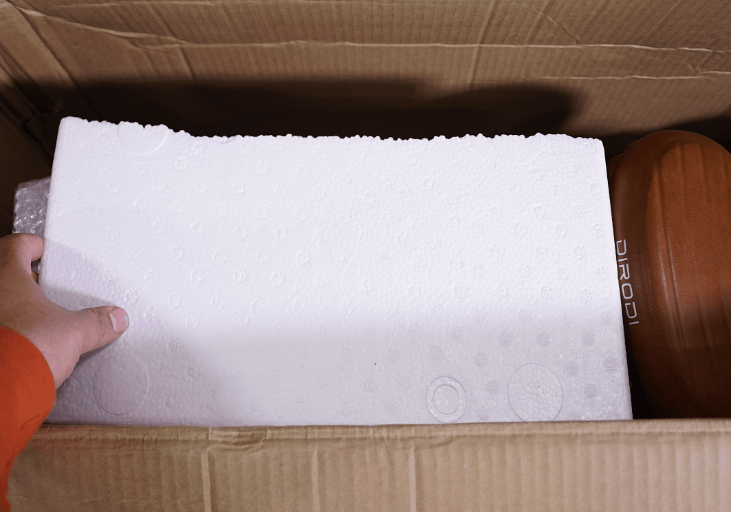
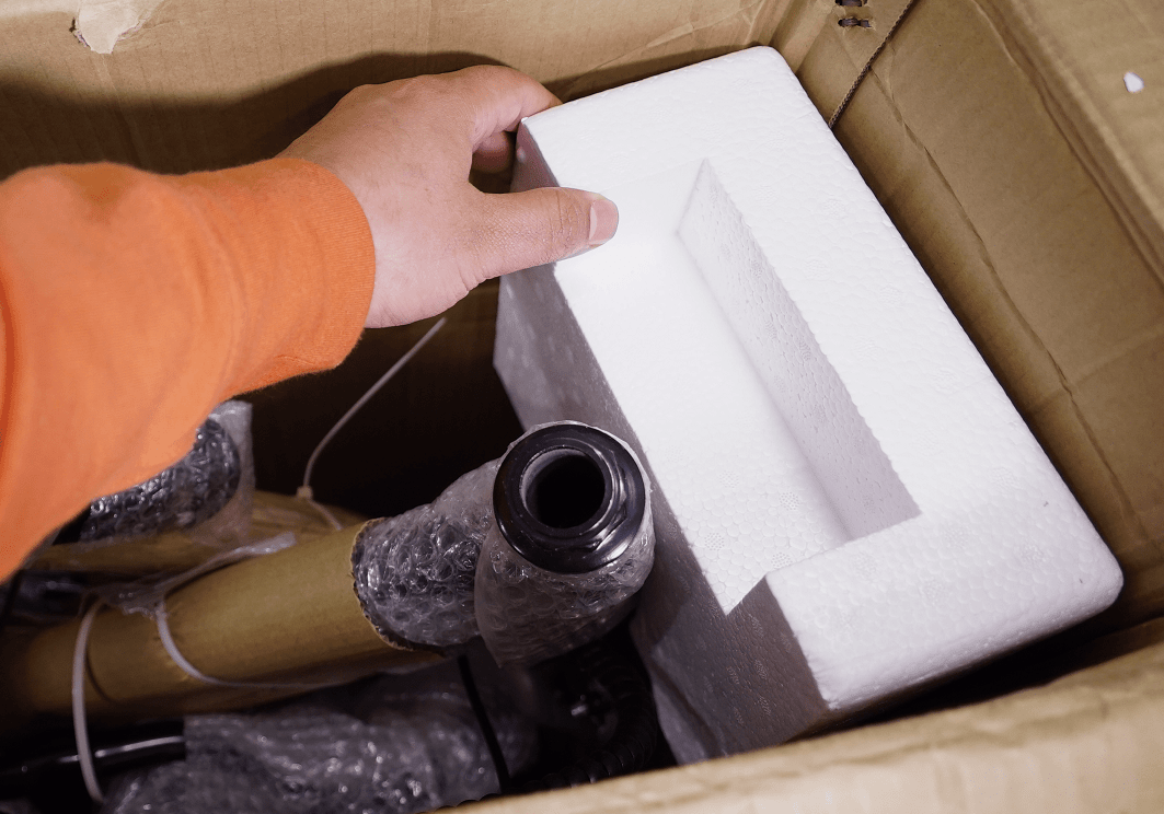
STEP 3
Remove the other loose protective foams
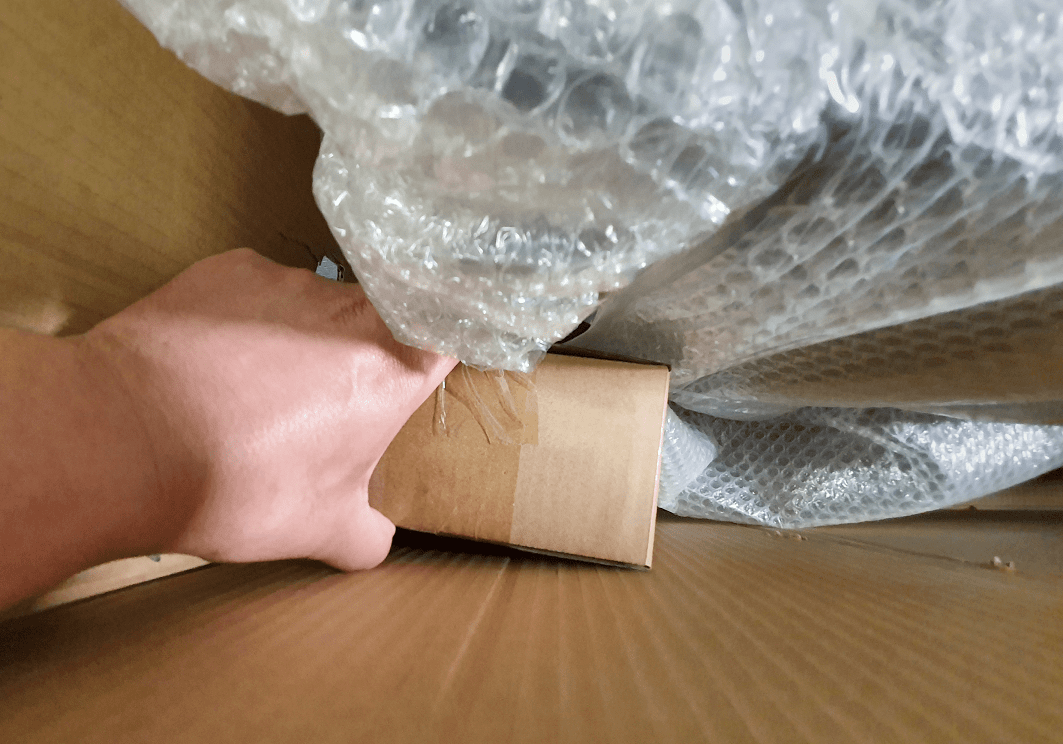
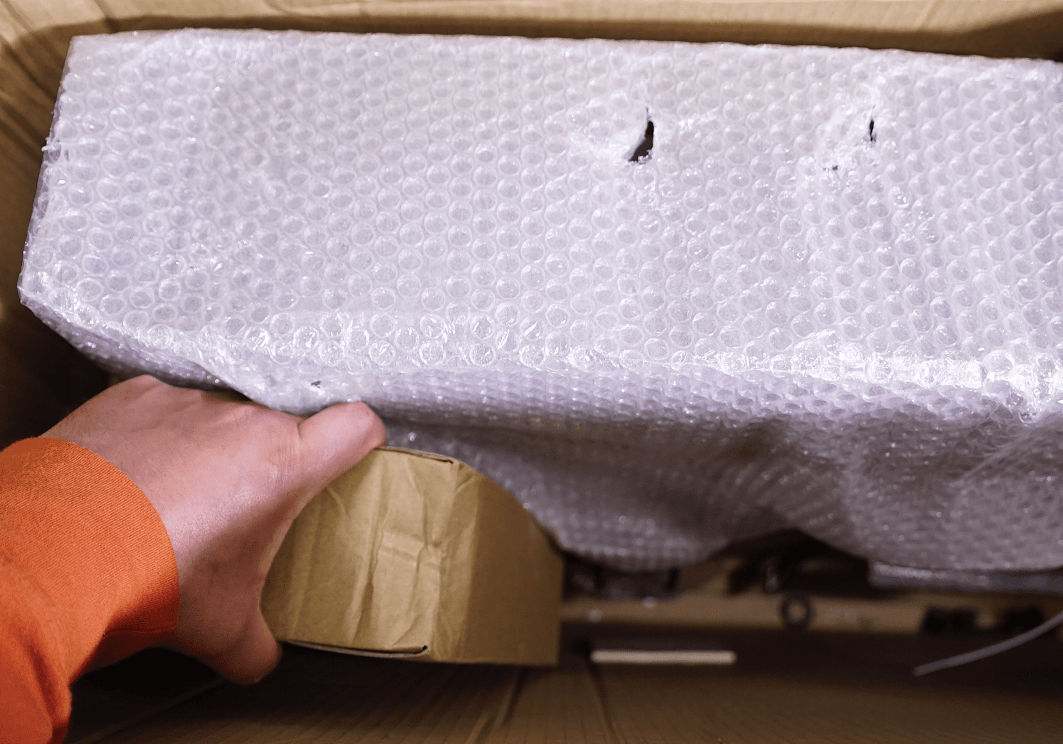
STEP 4
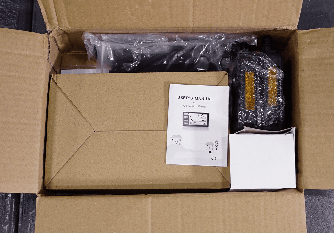
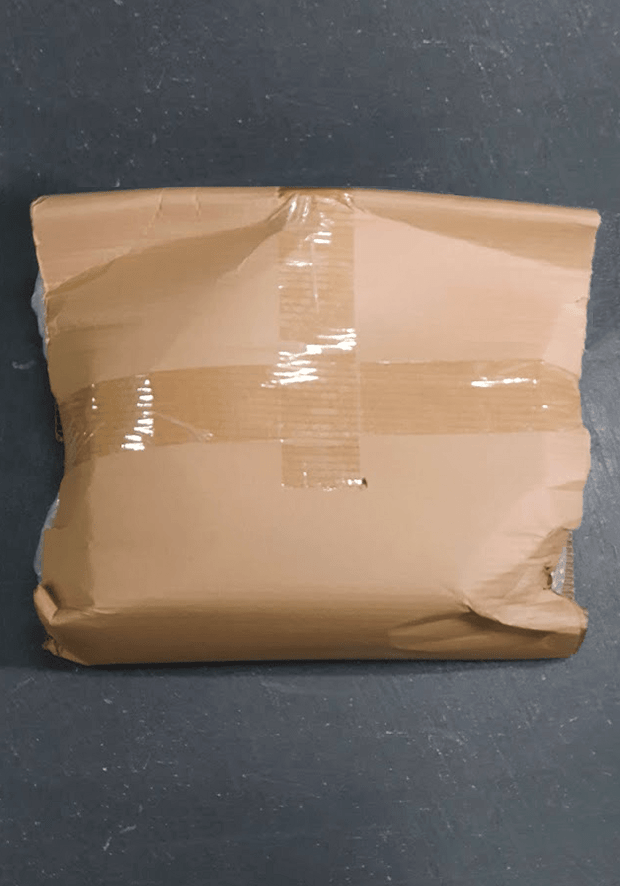
Remove the small accessories box
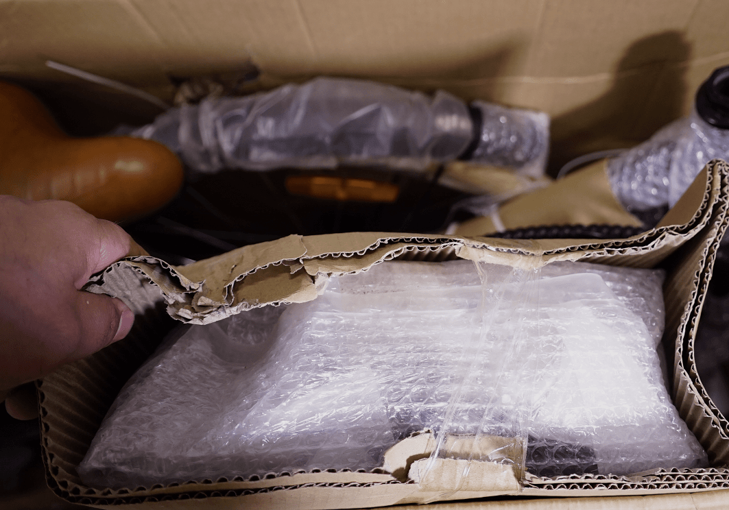
STEP 5
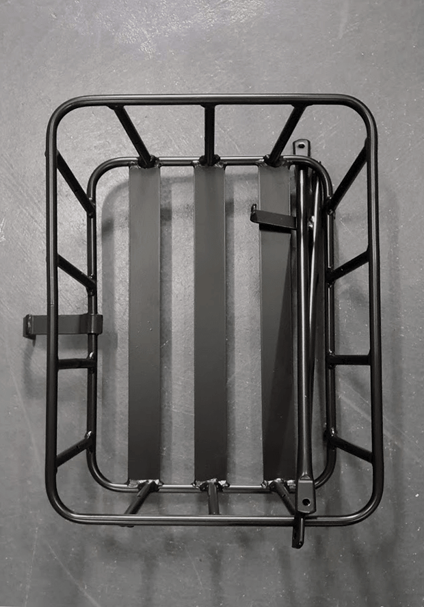
Remove the front carrier
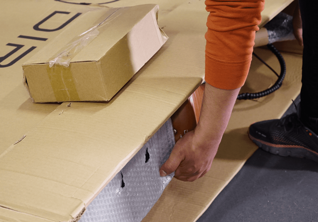
STEP 6
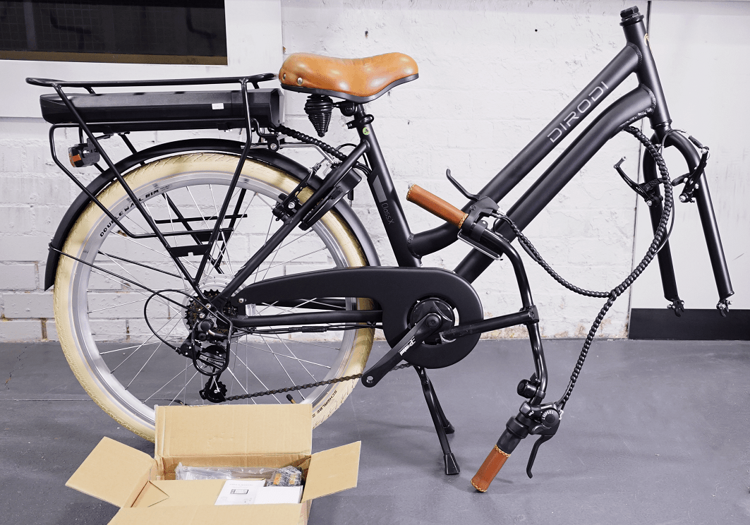
Lay the carton on the floor and pull the bike out of the carton.
It is better to put a mat in front of the carton so that the bike frame does not get scratched.
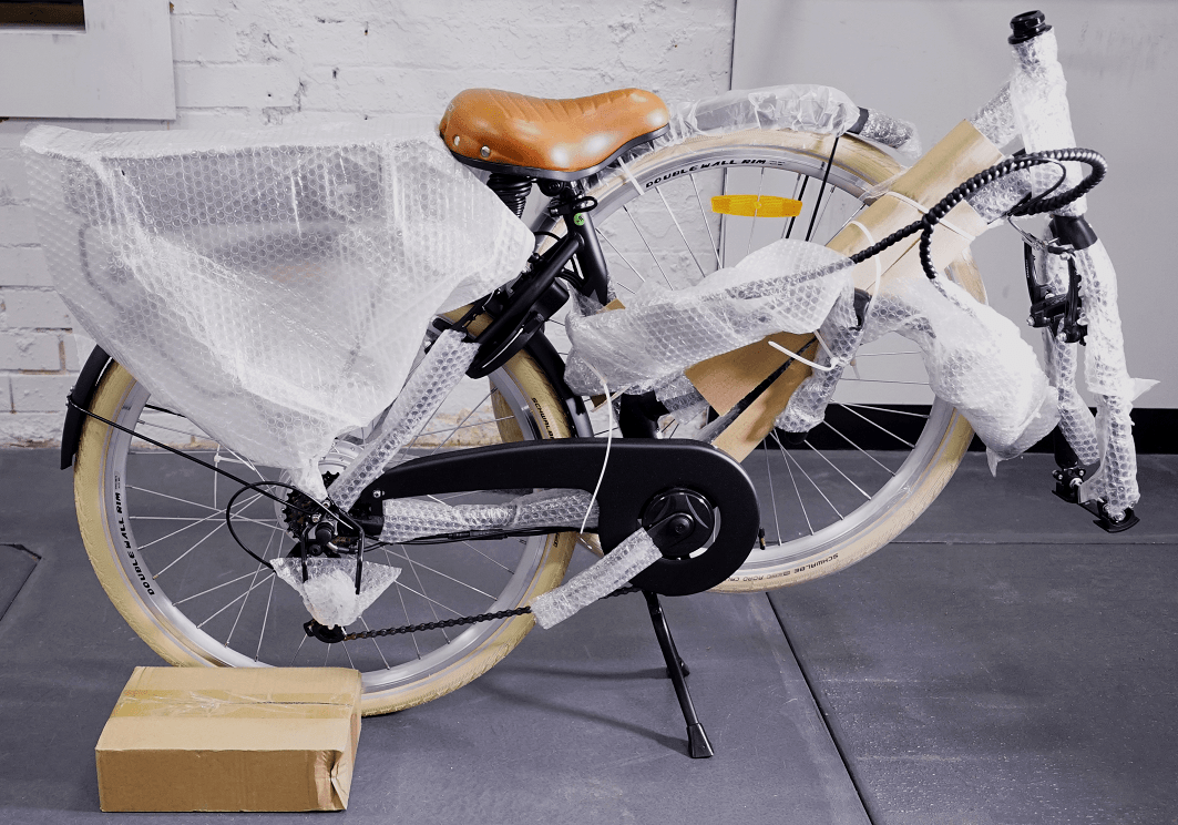
STEP 7
Put the bike in a standing position
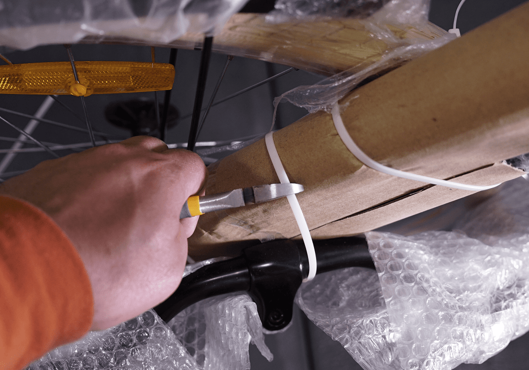
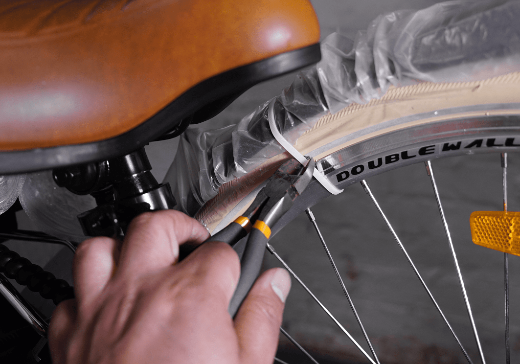
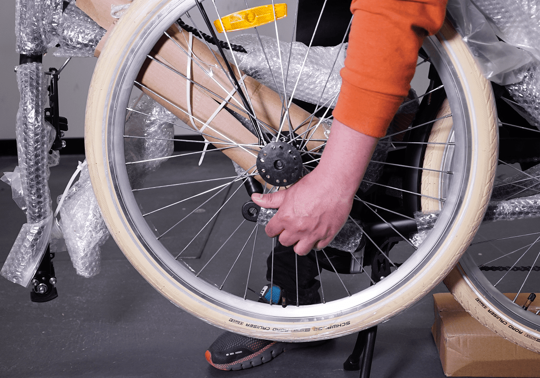
CHAPTER 3: REMOVING PROTECTIVE MATERIAL
STEP 1
Remove all protective material from the bike.
IMPORTANT: Please take care so that the bike frame does not get scratched.
STEP 2
Remove the front wheel off of the crank arm.
In order to release the wheel from the crank arm, it might be easier if you lift the rear wheel and turn the left pedal anti-clockwise a bit and then remove the wheel from the crank arm.
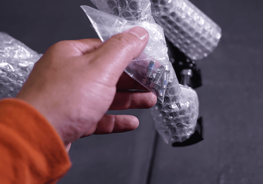
STEP 3
Find the small bag of 4 small bolts, which will be used for rear basket assembly.
The plastic bag is usually attached to the bike’s front forks
STEP 4
Remove the plastic fork protector from the front fork
STEP 5
Remove the steel fork protector from the front fork by loosening the nuts on both sides
STEP 6
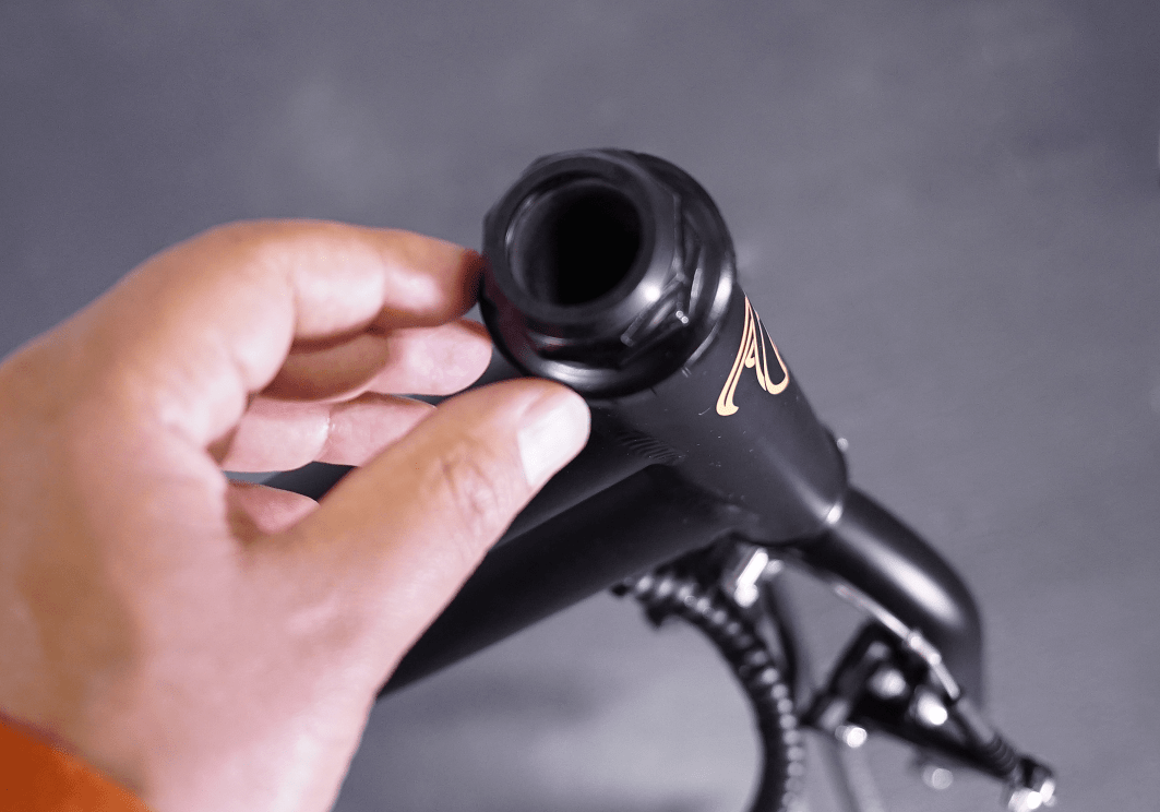
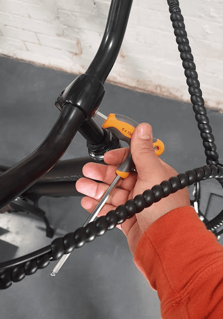
Remove the plastic cap from the handlebar stem
STEP 7
Open the accessories box.
(Which includes the power adapter, basic assembly tools, front light, pedals, bike’s manual and LCD’s manual)
STEP 8
After all protective materials are removed, your bike should look the same as that the photo.
CHAPTER 4: HANDLEBARS ASSEMBLY
STEP 1
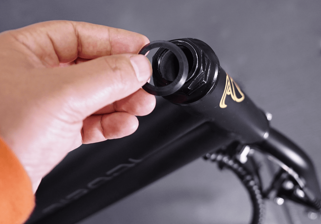
On some versions of ClassX, a plastic washer is provided, which should be put on top of the bike head tube
STEP 2
Rotate the forks of the bike by 180 degree anti-clockwise.
After the adjustment is done, the bike's brakes should be in front of the forks.
STEP 3
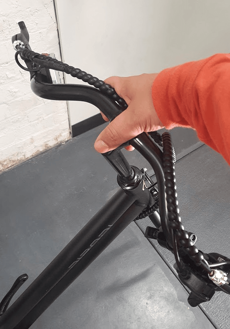
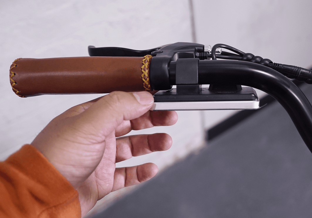
Insert the stem into the headtube, adjust the height and angle of the handlebars and fasten the two bolts on the stem
STEP 4
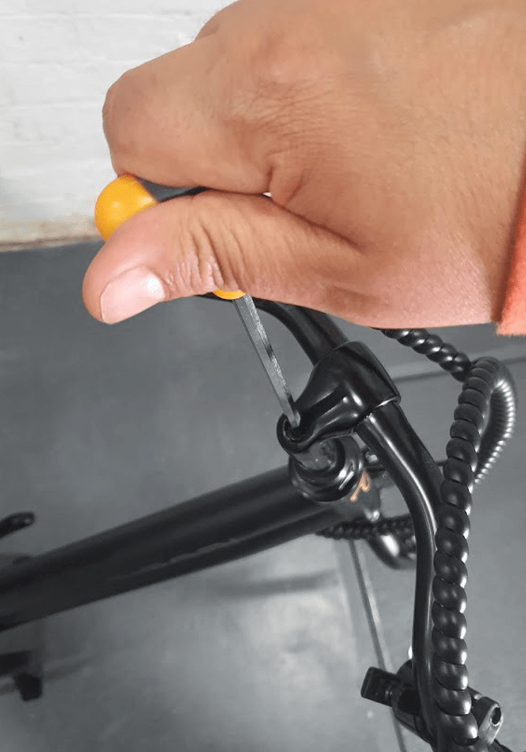
Now adjust the angle of the display

CHAPTER 5: FRONT WHEEL ASSEMBLY
STEP 1
** Please note for the front wheel assembly, the bike should not be on kickstand.
Remove plastic protectors from each side of the front wheel
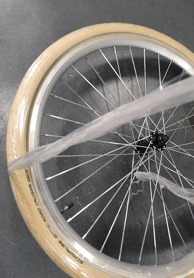
STEP 2
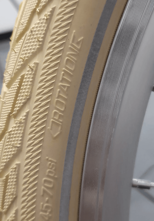
Remove the plastic wrap from the tyre (photo 3). After this step is done, the tyre should look the same as that in photo
STEP 3
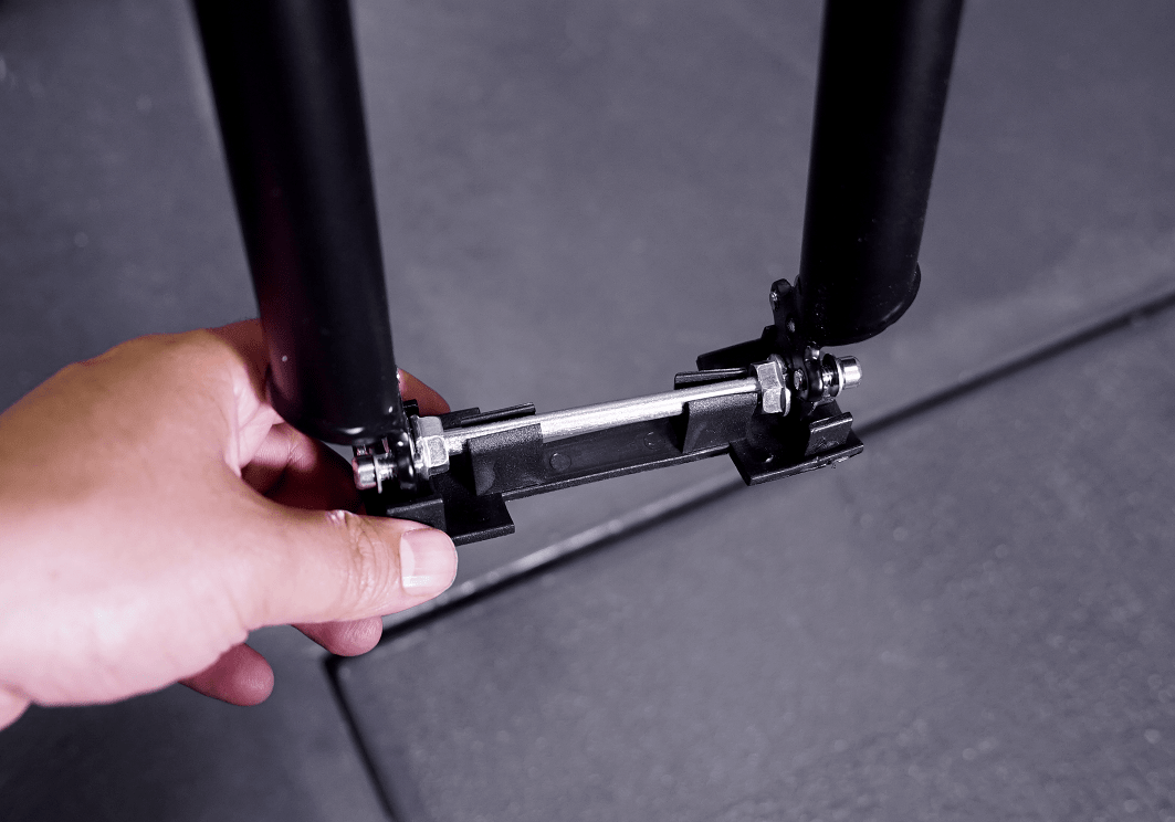
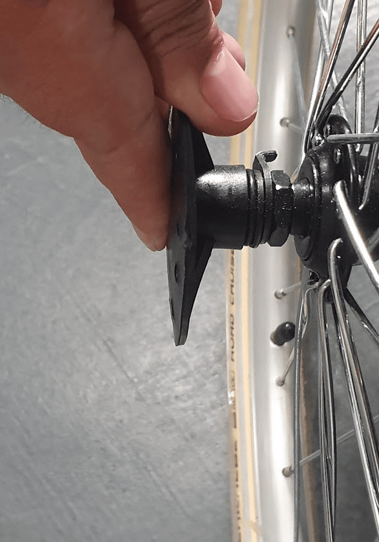
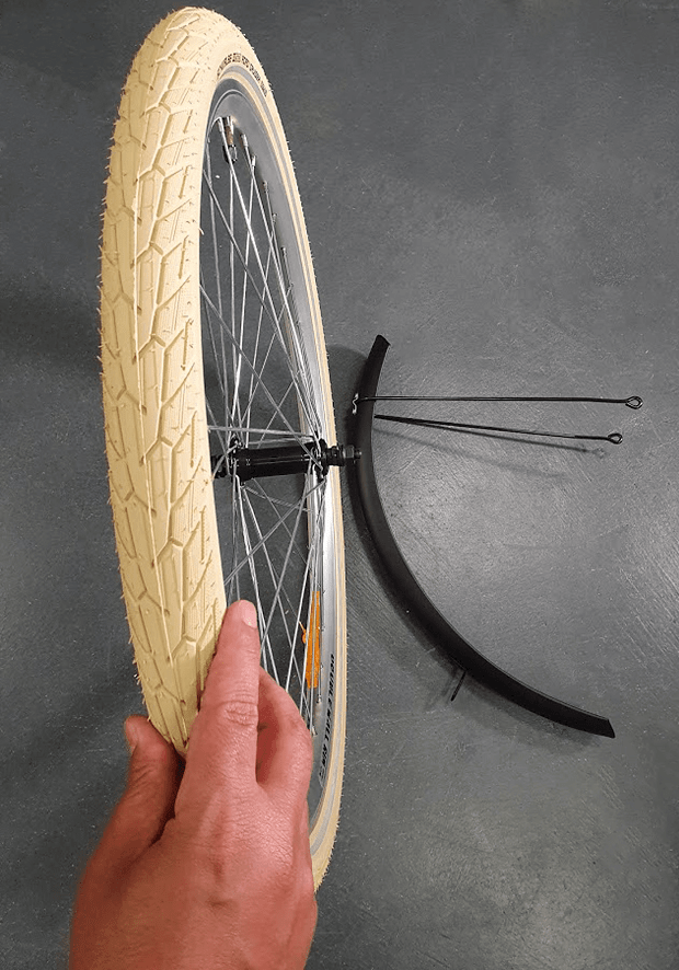
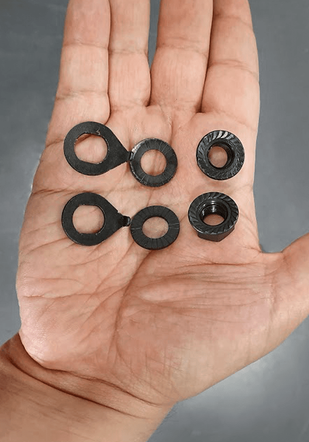
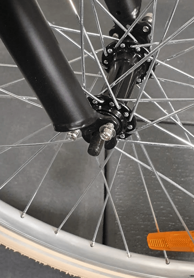
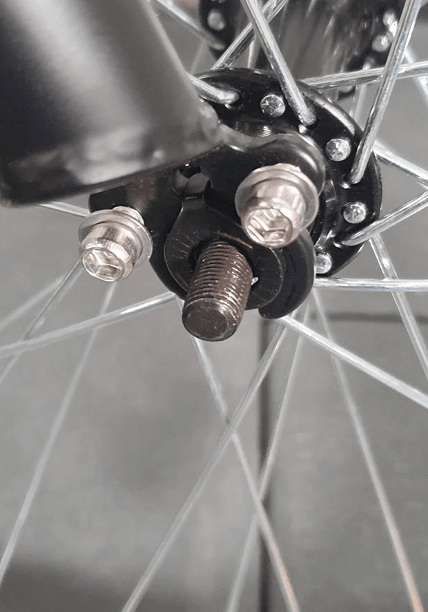
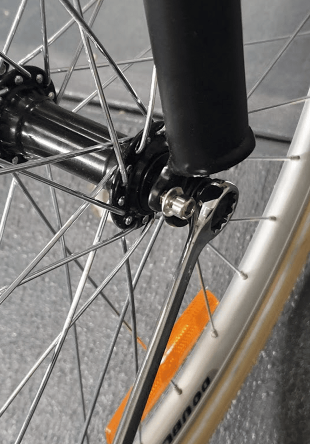
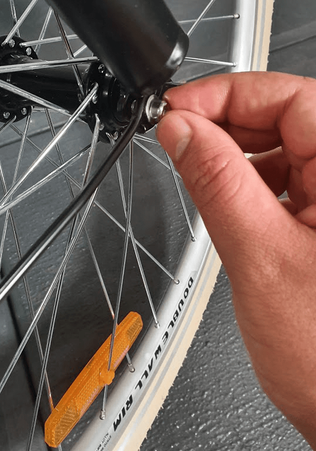
Remove one nut and 2 washers from each side of the wheel
STEP 4
Pressing the brake arms towards each other and release the brake noodle from the noodle holder
STEP 5
Lift the bike and carefully lower the forks until the wheel axel fits nicely in the front
Ensure the rotation sign on the tyre is facing the correct direction
STEP 6
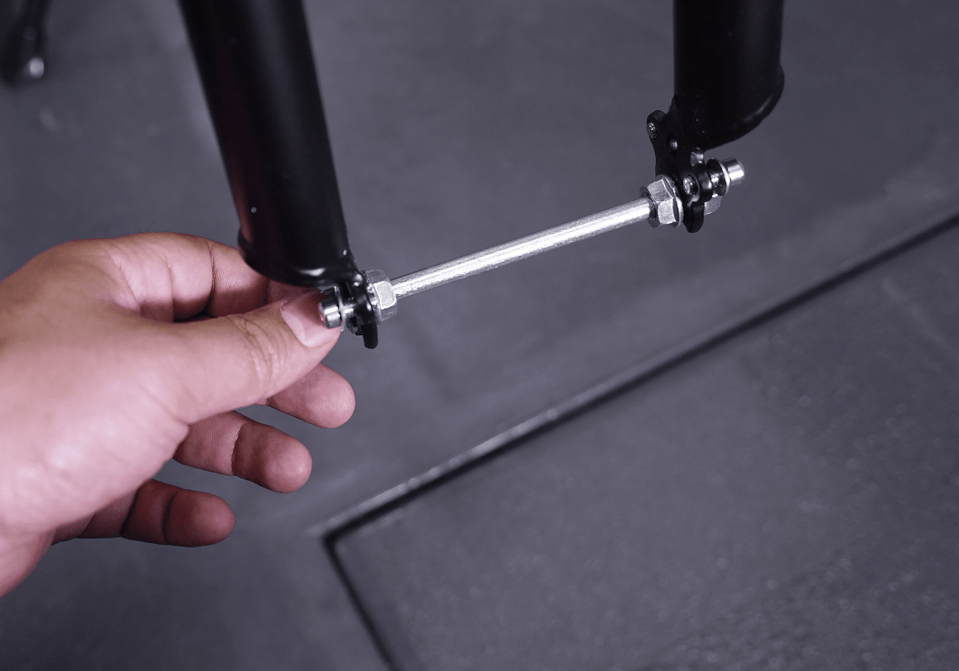
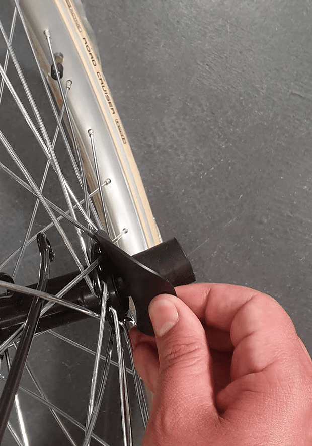
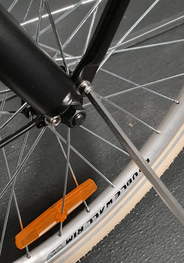
Insert the locking washer to the axel on the right and ensure it is locked just as shown in photo
**Please note the washer tap should be inserted in the hole on the fork so that it locks.
STEP 7
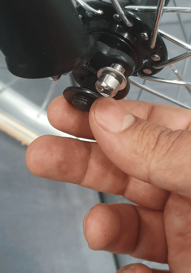
Then insert the second washer (photo 12) followed by the nut
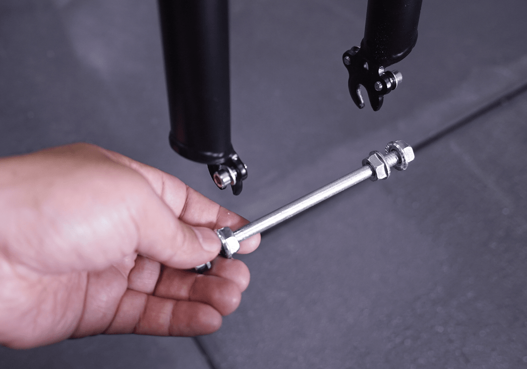
STEP 8
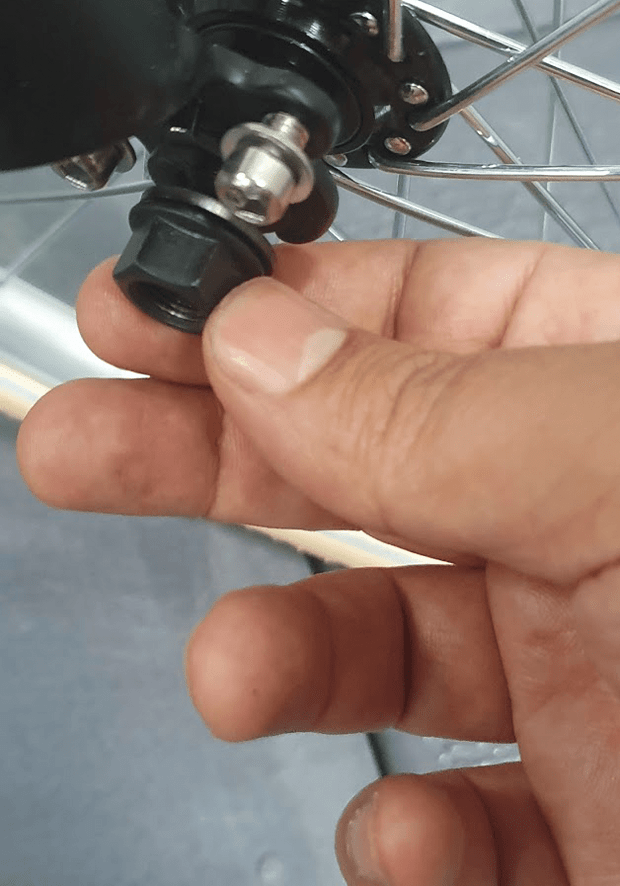
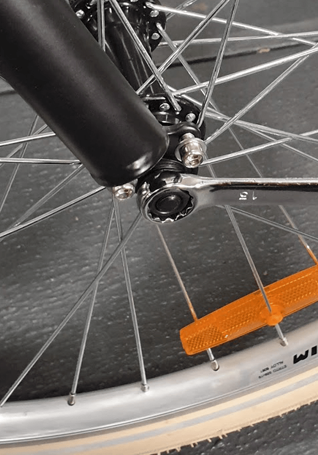
Then hand tighten the nut. Do the same on the left. Now by using a wrench tighten the nut on one side a bit and then do the same on the other side
Repeat tightening each side a bit until the nuts on both sides are fully tightened. You should keep the tyre in the middle of the forks while you are tightening the nuts (The distance from each side of the tyre to the fork should be almost the same).
CHAPTER 6: FRONT MUDGUARD, CARRIER & LIGHT ASSEMBLY
STEP 1
IMPORTANT: Please note in this step, you should half tighten all nuts and bolts until the assembly of the mudguard and the front carrier is finished. After the assembly is done, then you should fully tighten all nuts and bolts.
Remove the protective packaging of the front carrier
STEP 2
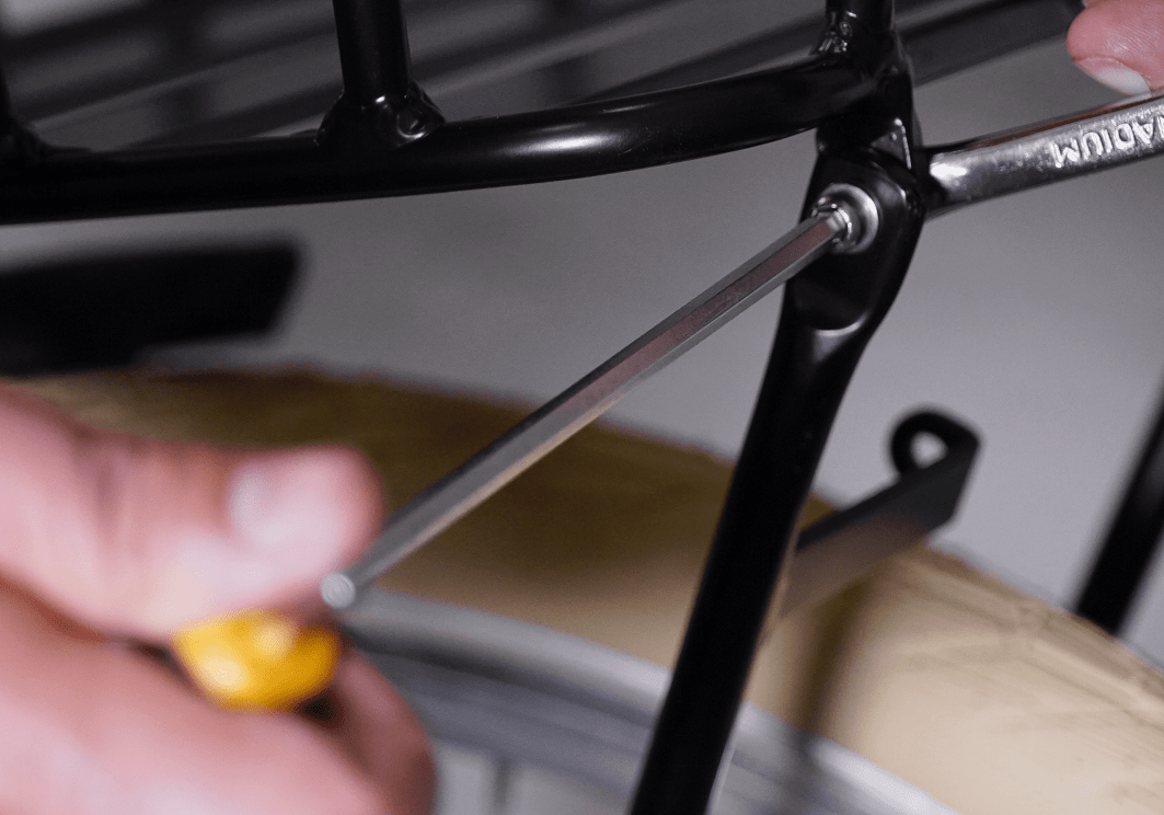
Remove the bolt, washers and the nut from top of the bike forks
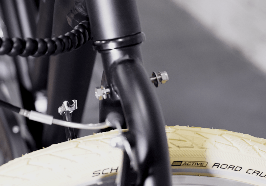
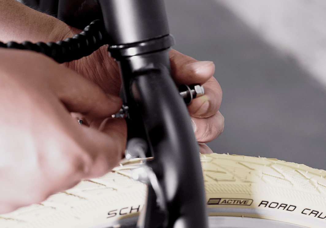
STEP 3
Take the mudguard and the front carrier and assemble them to top of the bike forks by using the bolt, washers and the nut removed in the previous step.
Please ensure the brake cable going to the left brake arm is under the bolt and carrier before tightening the nut. Half tighten the nut by using two wrenches at the same time
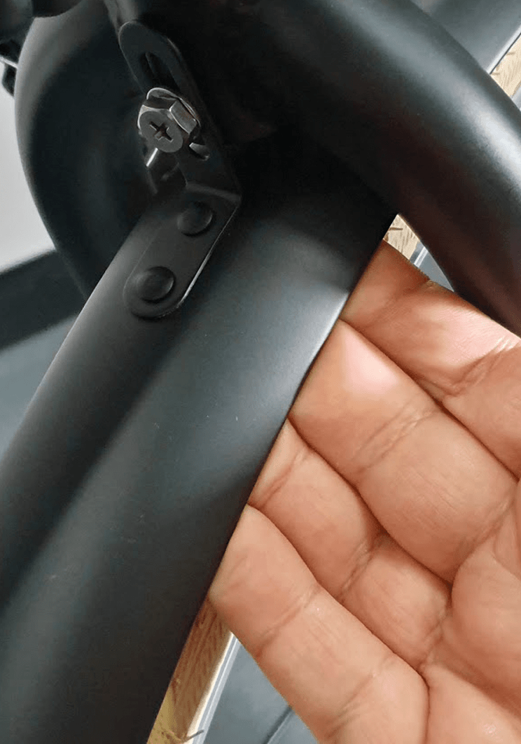
IMPORTANT: ClassX front carrier is hand made and on some of the carriers, the front bracket does not sit completely flush. If that’s the case, please refer to the video below to correct the angle of the front carrier’s bracket.
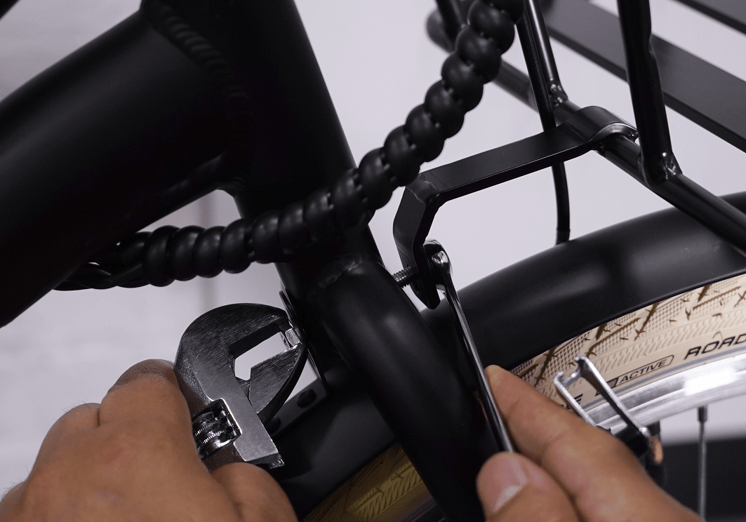
STEP 4
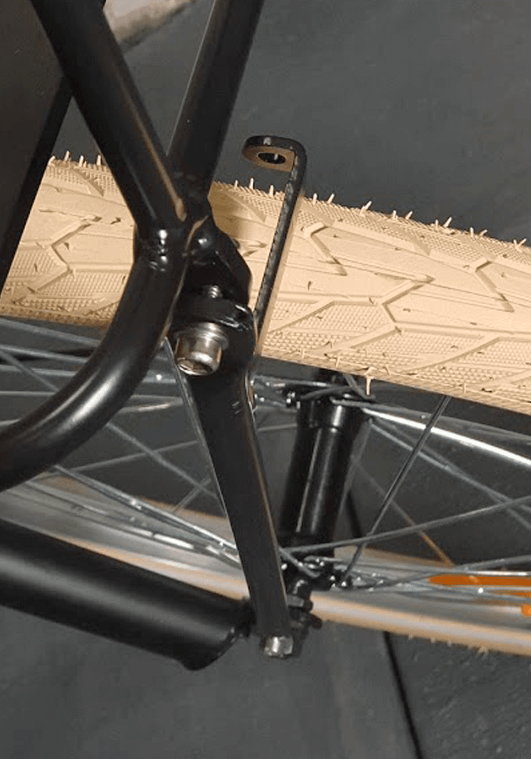
Using a bolt, semi-tighten the mudguard brace to the right fork . Do the same on the other side
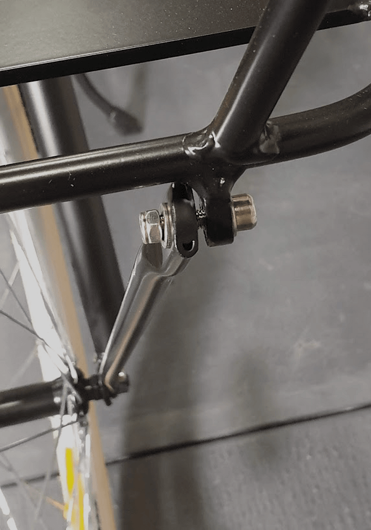
STEP 5
Now take the bar that has a bracket for the front light assembly and semi tighten it to the right fork and the front
IMPORTANT: Please note the bar should be placed to the right side of the bracket on the front carrier if you are on the bike and looking towards the carrier
STEP 6
Do the same on the other side
IMPORTANT: Please note the bar should be placed to the right side of the bracket on the front carrier if you are on the bike and looking towards the carrier
STEP 7
Now push the mudguard away from the tyre so that the tyre does not rub against the mudguard and fully tighten the nut by using two wrenches at the same
Now fully tighten all bolts on the forks and on the front carrier.
STEP 8
Now remove the bolt, washer and the nut from the front light by using an Allen key and a wrench
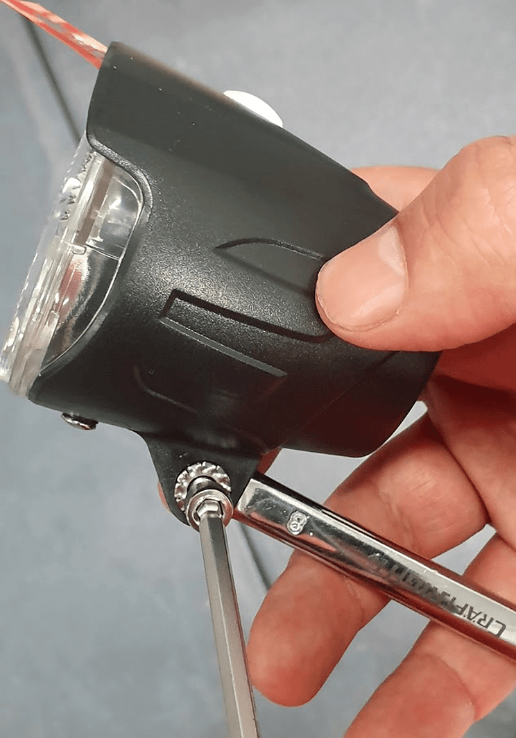
STEP 9
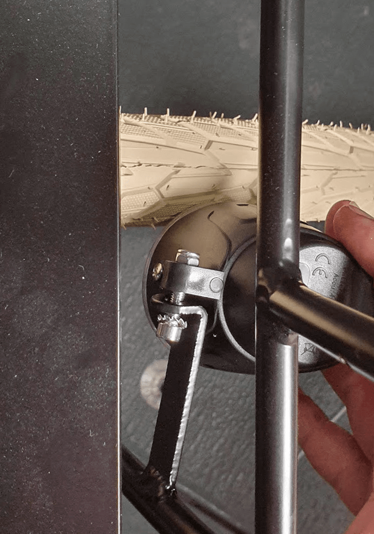
Now assemble the front light to the front light bracket on the right carrier bar using an Allen key and a wrench
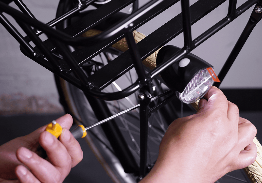
STEP 10
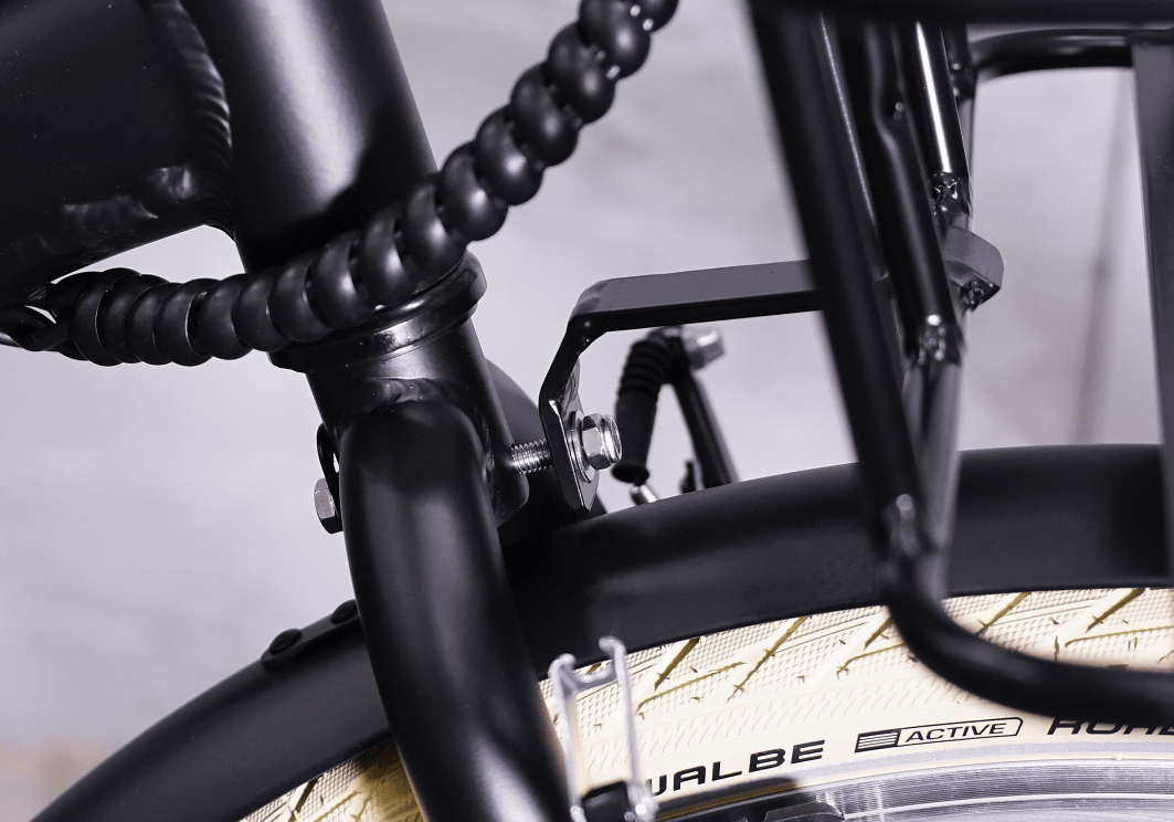
Now you are done with this step. In rare cases, if the mudguard is not align with the tyre you must remove one of the screws that attaches the mudguard braces to the mudguard, align the mudguard to the tyre and fasten the screw again
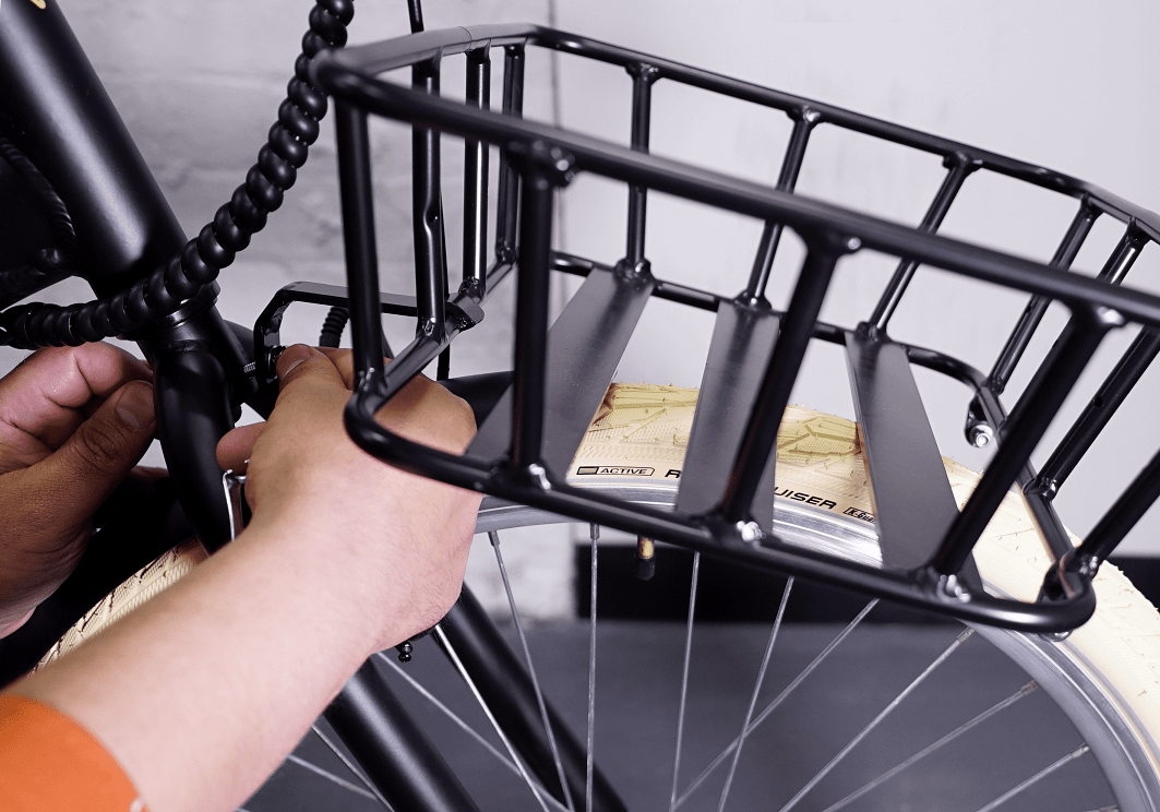
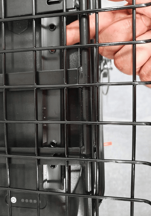
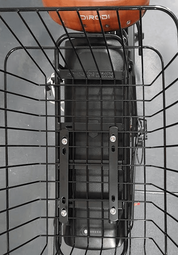
CHAPTER 7: REAR BASKET ASSEMBLY
IMPORTANT: Please note the steel basket should be assembled as far as possible to the bike saddle. Otherwise, when you sit on the saddle, your back might rub against the basket.
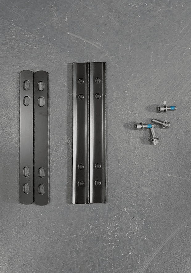
This step requires 2 flat bars, 2 curved bars and four small bolts as shown in photo
Please note the longer black bolts will not be used.
STEP 2
Put the steel basket on top of the bike carrier. Put one of the curved bars under the bike’s carrier. The curved section of the bar (the hill) should face downward
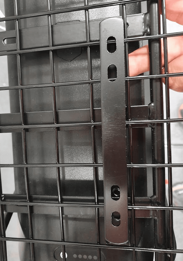
STEP 3
Now put one of the flat bars on the bike steel basket in such a way that the outer holes on both bars are aligned
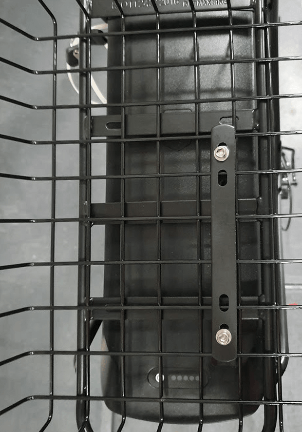
STEP 4
Using the two bolts, half tighten the two bars together (photo 4). Do the same on the other side.
IMPORTANT: Please note the bolts do not need to pass through the holes on the carrier
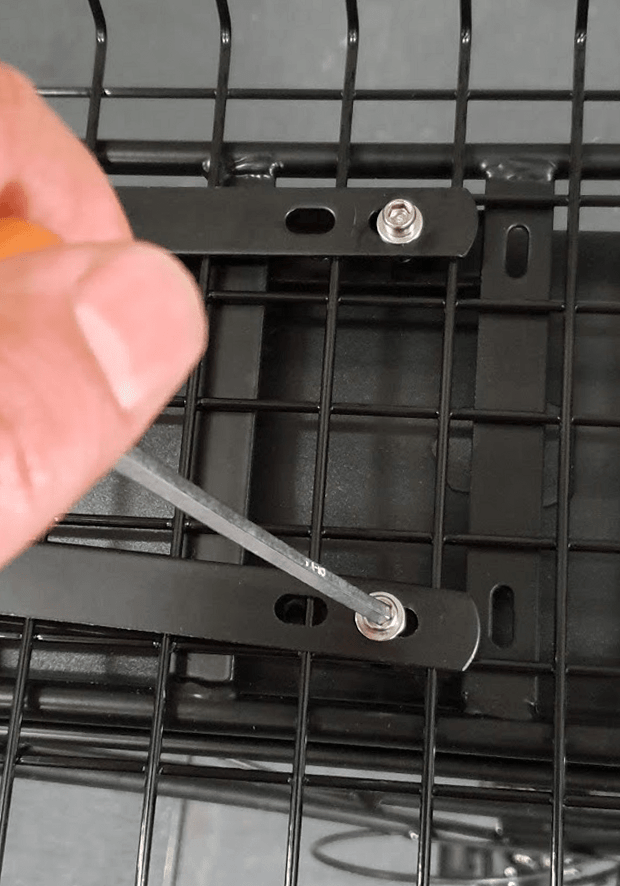
STEP 5
Now fully tighten all bolts
STEP 6
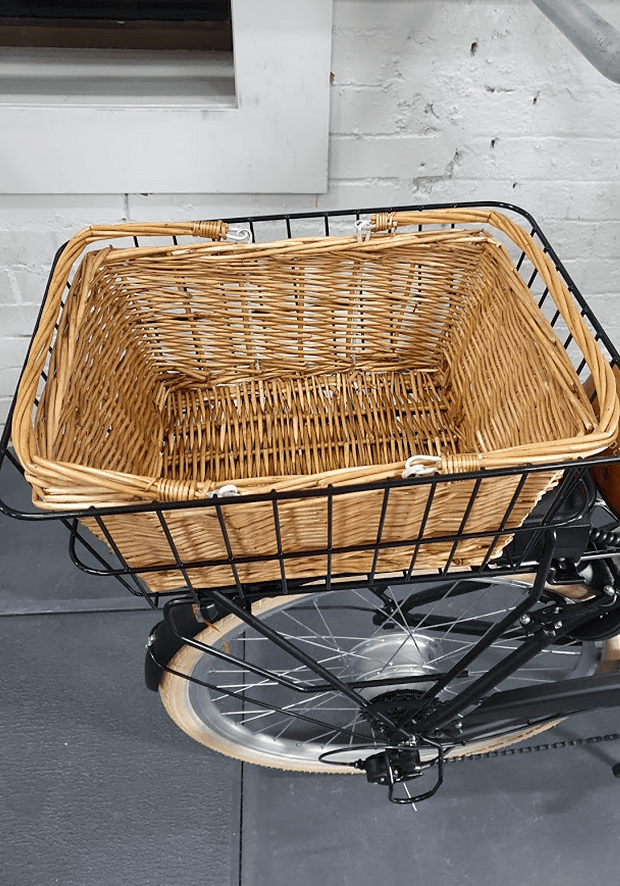
Put the wicker basket inside the steel basket
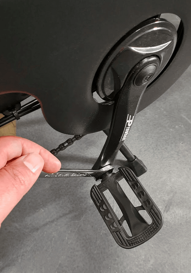
CHAPTER 8: INSTALLING PEDALS
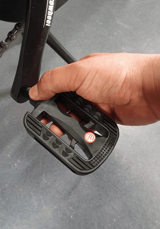
STEP 1
Tighten the right pedal to the right crank by turning it clock wise by hand (photo 1).
You should be able to tighten the pedal almost all the way down by your hand.
IMPORTANT: This step is sensitive, if done wrong, the threads on the pedal or the crank might get stripped. You should tighten the pedals by hand as much as possible and then fully tighten them by using a wrench.
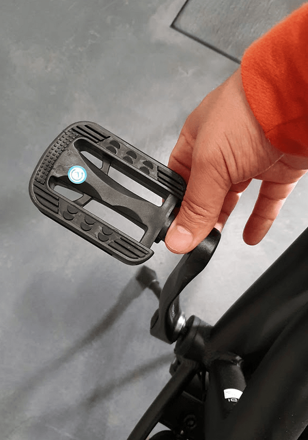
STEP 2
Tighten the left pedal to the left crank by turning it anti-clock wise by hand (photo2).
You should be able to tighten the pedal almost all the way down by your hand.
STEP 3
Then tighten both pedals fully by using a wrench
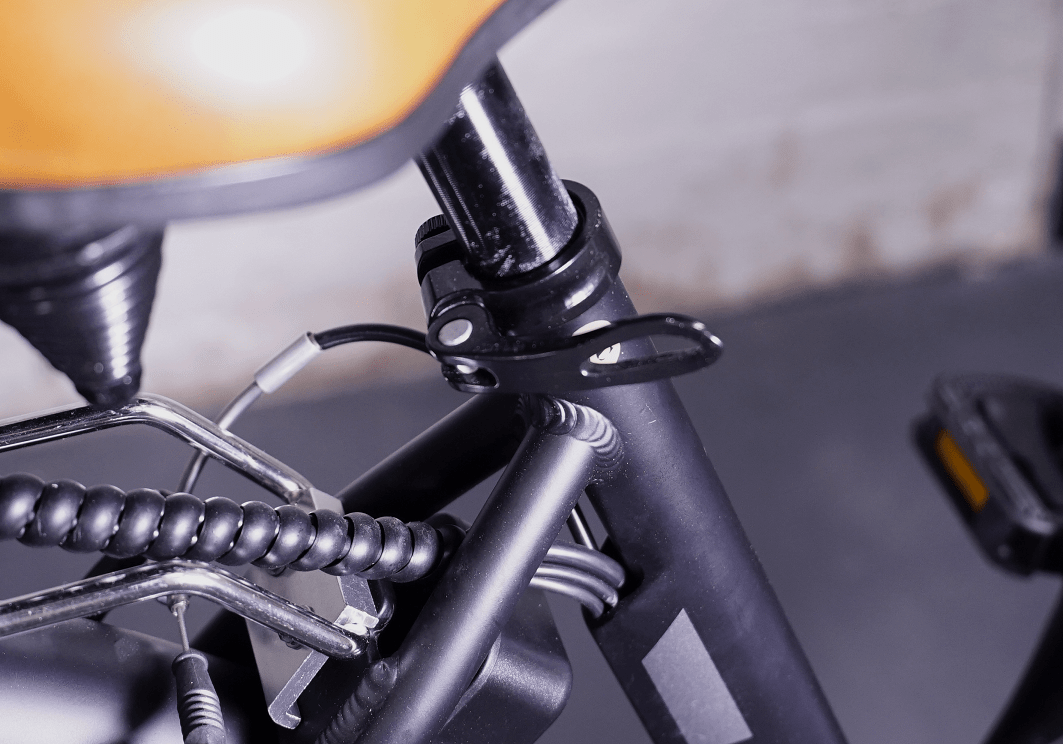
CHAPTER 9: ADJUSTING THE SADDLE
STEP 1
Open the lever and loosen the bolt on the seat post clamp
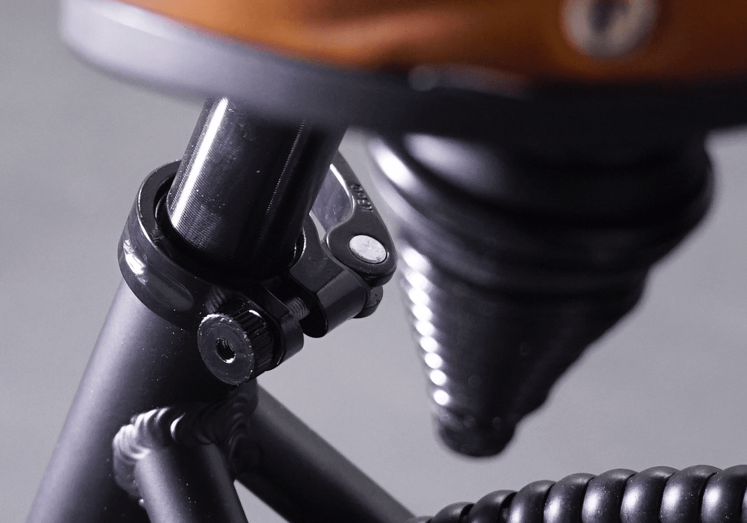
STEP 2
Adjust the seat height, tighten the bolt on the seat clamp until the lever on the clamp becomes firm to close. Now close the lever
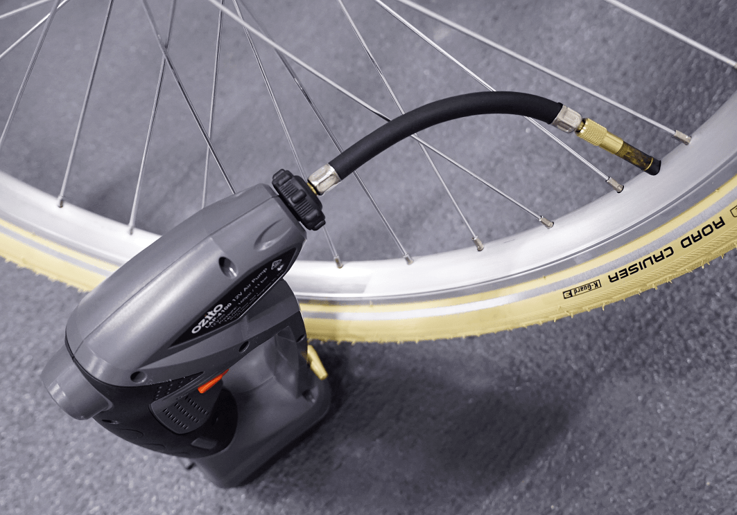
CHAPTER 10: PUMPING THE TYRES
STEP 1
Pump front and rear tyres. Tyre pressure should be in the range specified on the tyre.
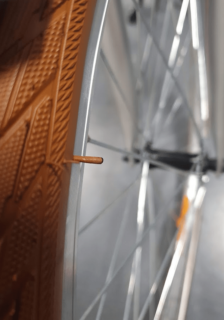
CHAPTER 11: REMOVING THICK RUBBER HAIRS ON TYRES
STEP 1
Please inspect both tyres, there might be one or two thick rubber hairs on each tyre .
Please remove them from the tyres as they might hit the brake pads or the wheel lock while you ride the bike and make some noise.
CHAPTER 12: REAR DERAILLEUR ADJUSTMENT
STEP 1
Rear Derailleur is adjusted in the factory but due to part movements during shipment, slight re-adjustments might be necessary. Derailleur adjustment are done by barrel adjuster and “H” and “L” screws as shown in photo 1. Please refer to the video in the link below:
How to Adjust a Rear Derailleur – Limit Screws & Indexing
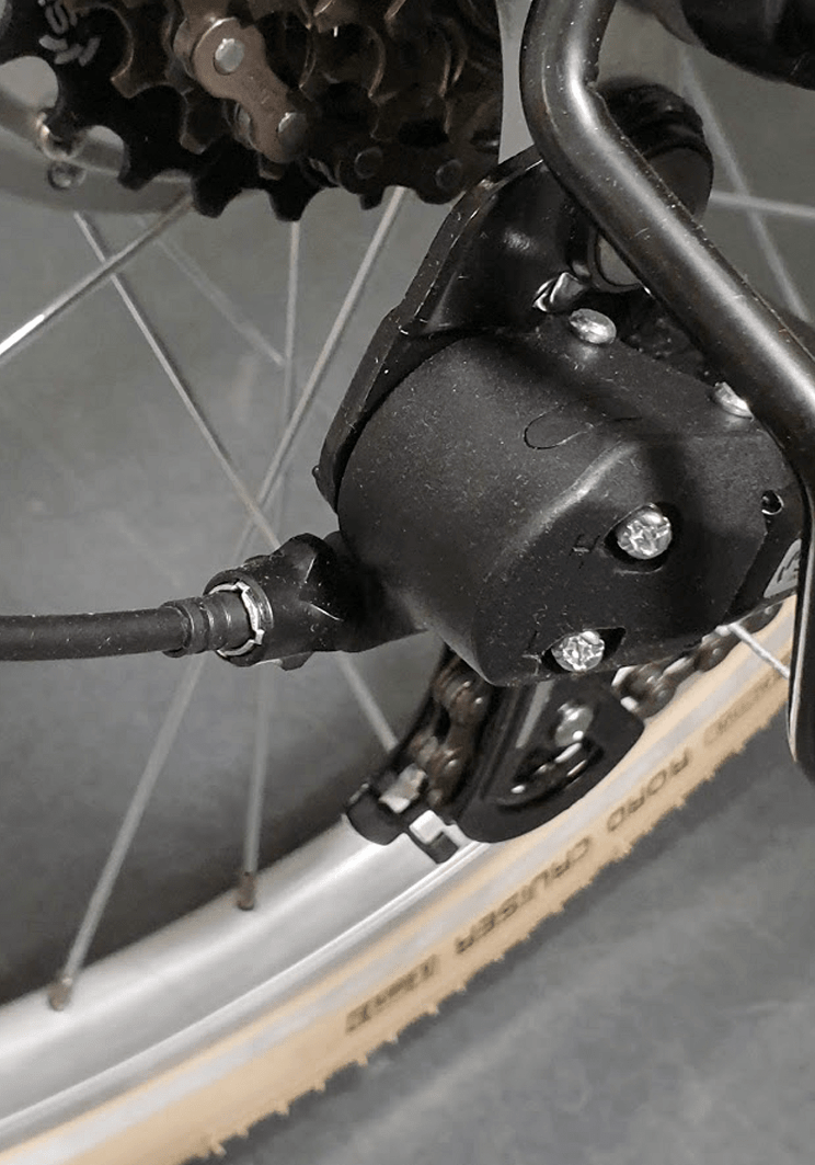
IMPORTANT: Please note as the derailleur is already adjusted in the factory, any issues in changing gear between gear #2 to #6, should be easily solved by turning the barrel adjuster (As per instructions in the video). After the gears are smoothly changed between gear #2 to #6, please test gear #1 (the largest cog) and #7
(the smallest cog). If you have any issues on gear #1, you need to adjust the “L” screw and if you have any issues on gear #7, you need to adjust the “H” screw as explained in the video.
CHAPTER 13: V-BRAKE ADJUSTMENT
STEP 1
Rear brake has been adjusted in the factory, so in general no further adjustment is required. For the front brake the steps are explained briefly below. If you require further information, please watch the video provided at the end of this section.
STEP 2
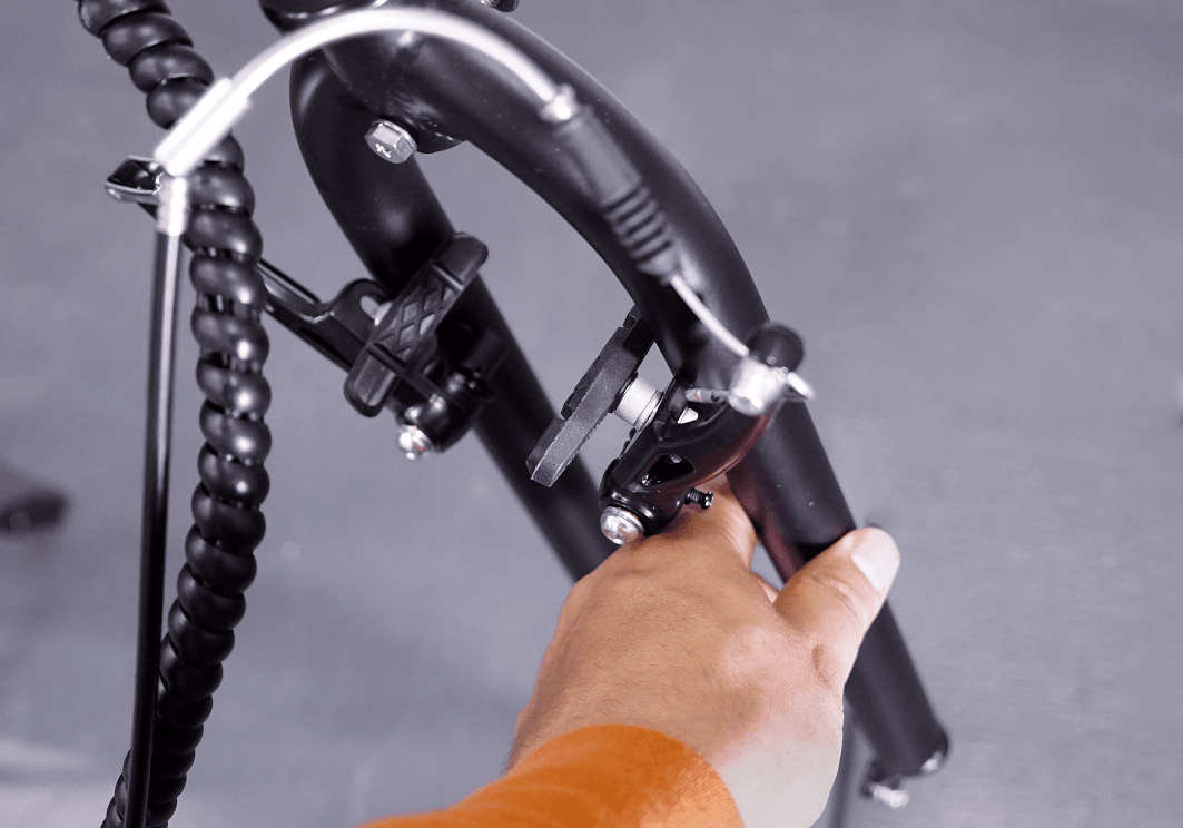
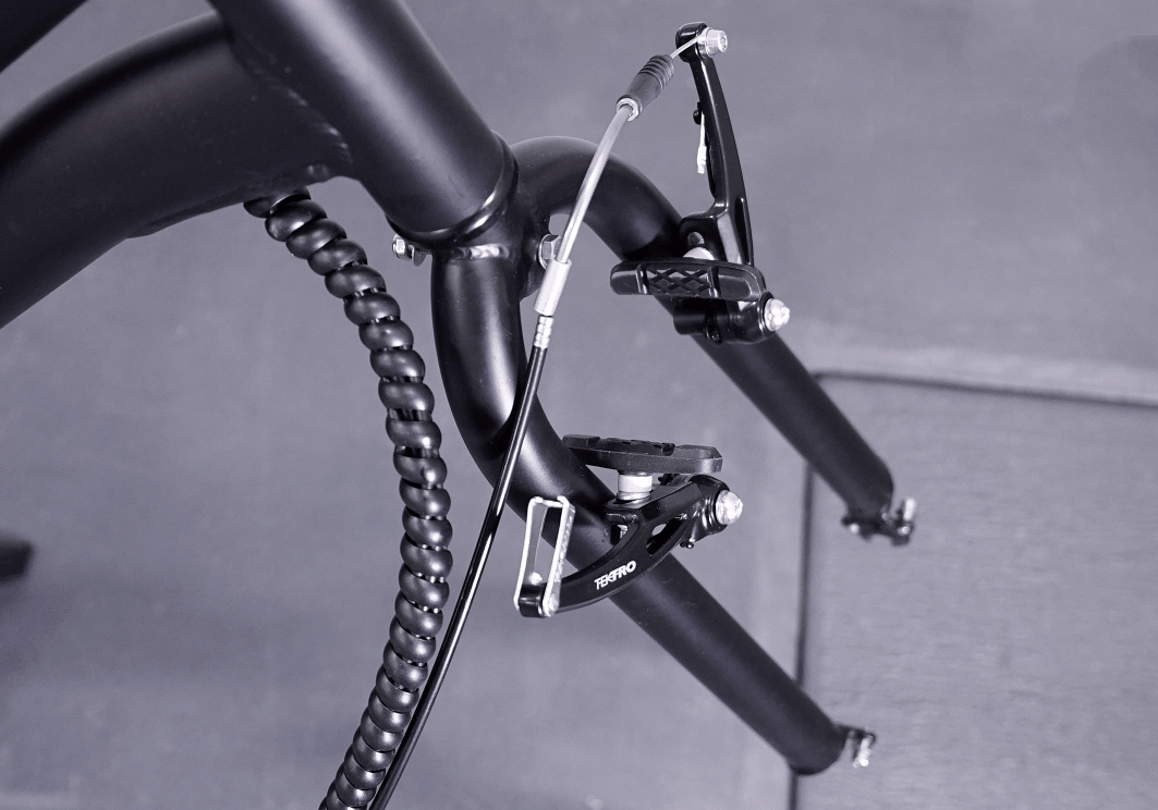
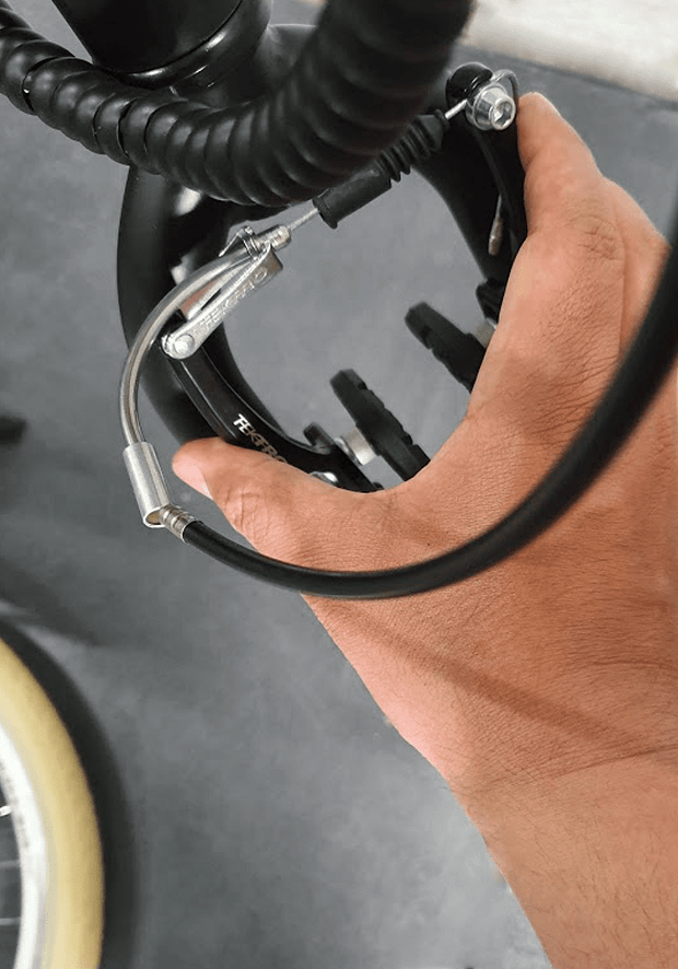
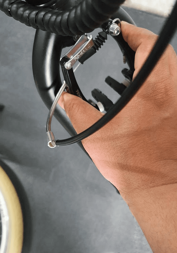
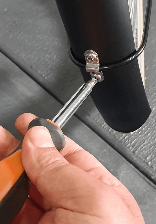
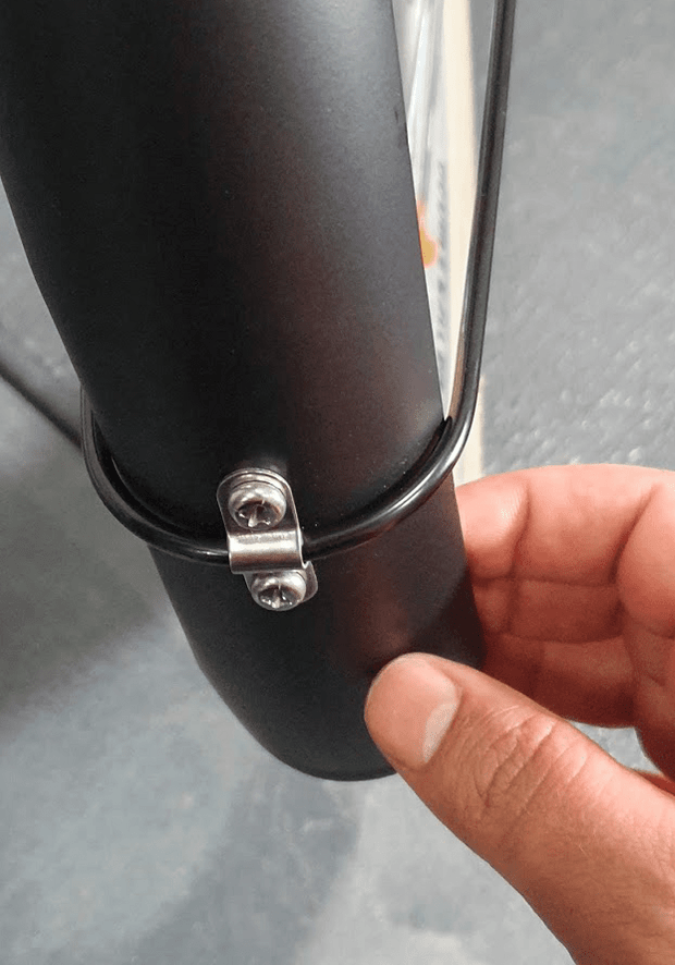
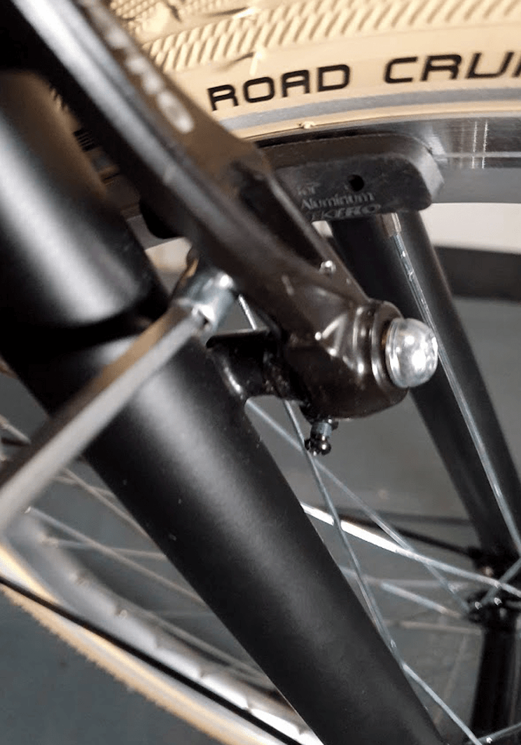
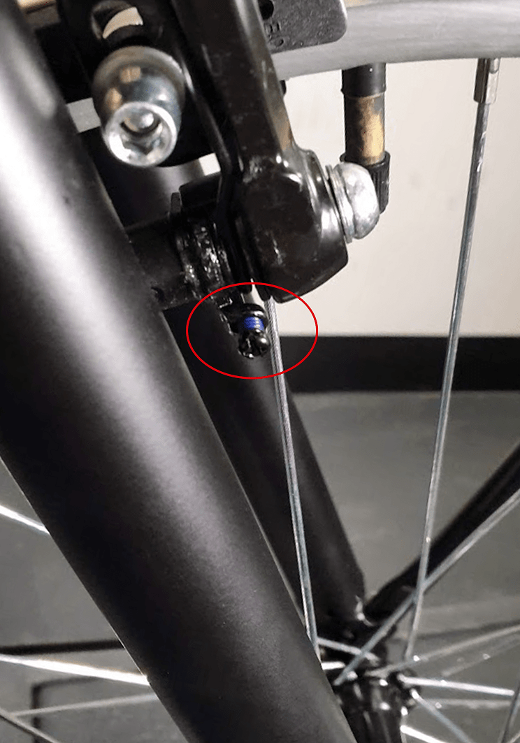
Using an Allen key, loosen the brake pad bolt on one side. Push the brake arm towards the wheel and adjust the brake pad so that it places exactly on the rim without touching the tire as shown in photo 1. Now, while holding the brake pad, tighten the bolt again. Do the same on the other side.
STEP 3
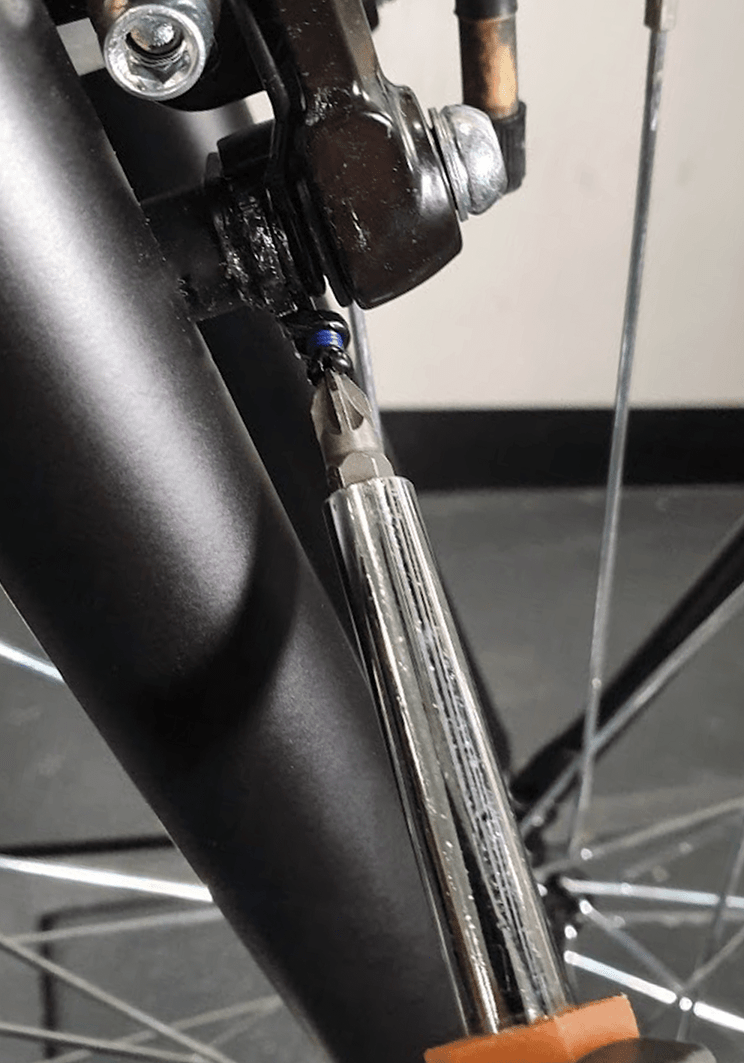
Push the brake levers towards each other and put the brake noodle inside the noodle holder (photo 2). If you can’t put the brake noodle inside the noodle holder because the cable is too short, then you should loosen the anchor bolt (highlighted in photo 2), extend the length of the brake cable and tighten the anchor bolt
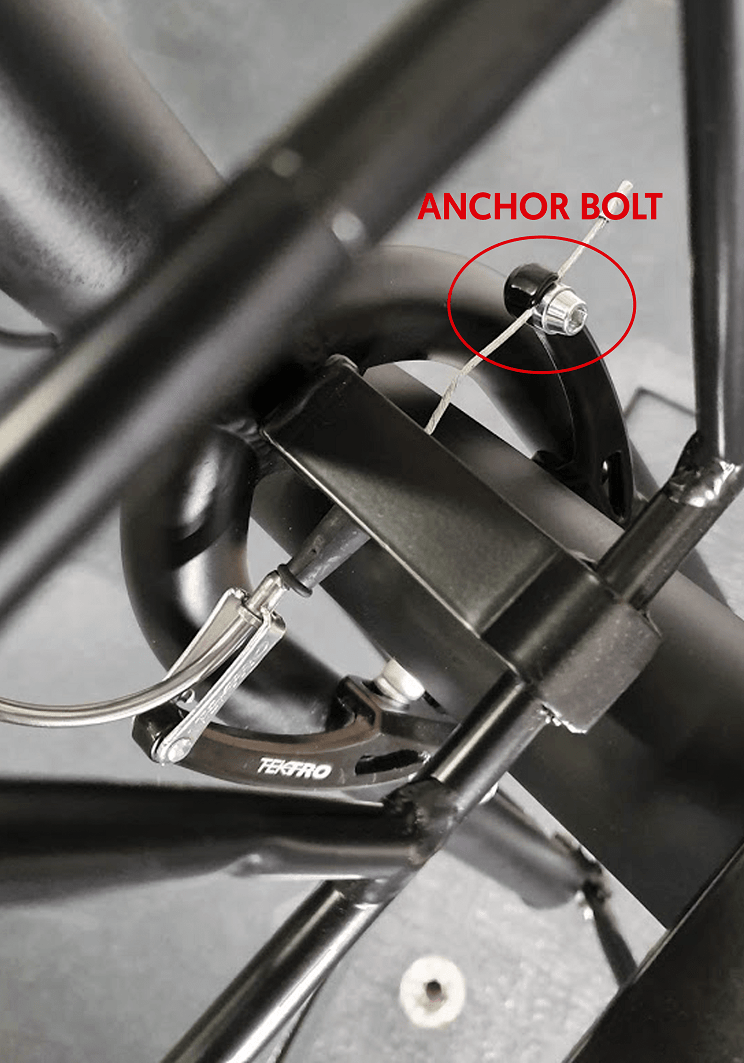
STEP 4
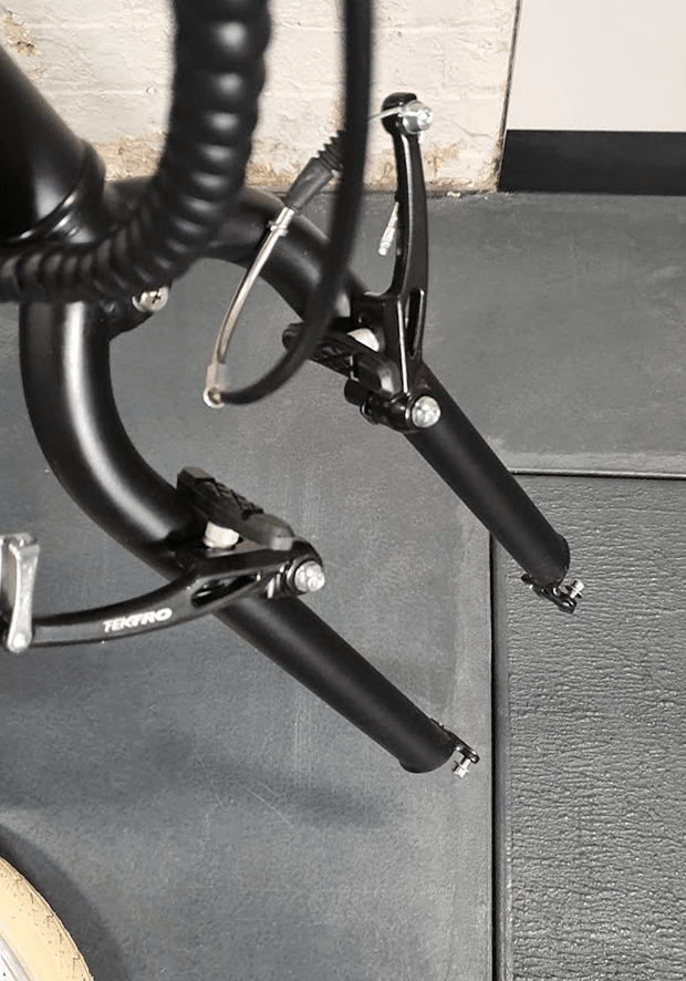
At this step, the distance from each brake pad to the rim might not be the same (we will center the brakes later in this step). However, the sum of space from both brake pads to the rim should not be more than 4 mm. You can adjust the distance of the brake pads to the rim by loosening the anchor bolt, adjusting the length of the brake cable, and tightening the bolt again.
STEP 5
If the right and left brake pads do not have the same distance from the rim, you can center the brakes by adjusting the "Spring tension centering screws" located on both brake arms.
On the side that is closer to the rim, you should tighten this screw a bit and on the side that is farther from the rim, loosen this screw a bit until the distance from both pads to the rim is the same. If you can’t make both brake pads having the same distance from the rim with the “spring tension centering screws”, then probably the wheel is not centered. In that case you should loosen the wheel nuts, center the wheel (so that each side of the tyre has the same distance to the bike’s fork) and then retry to center the brake pads.
STEP 6
If you are still having difficulties adjusting the brakes, please watch the video below for more detailed information on how to adjust v Please watch the video from 3:40 to 13:30.
CHAPTER 14: OPERATING THE BIKE
STEP 1
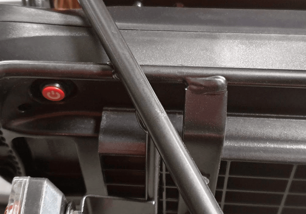
Turning on and riding the bike: Press in the red switch under the battery (The switch is highlighted in photo).
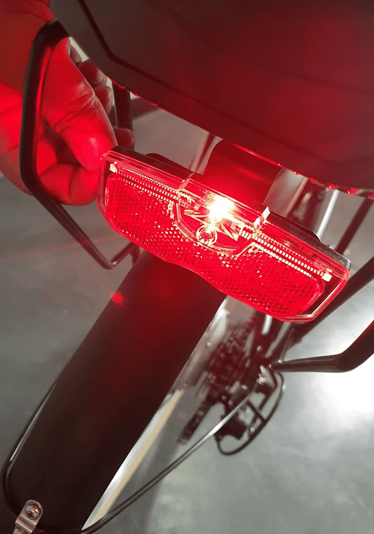
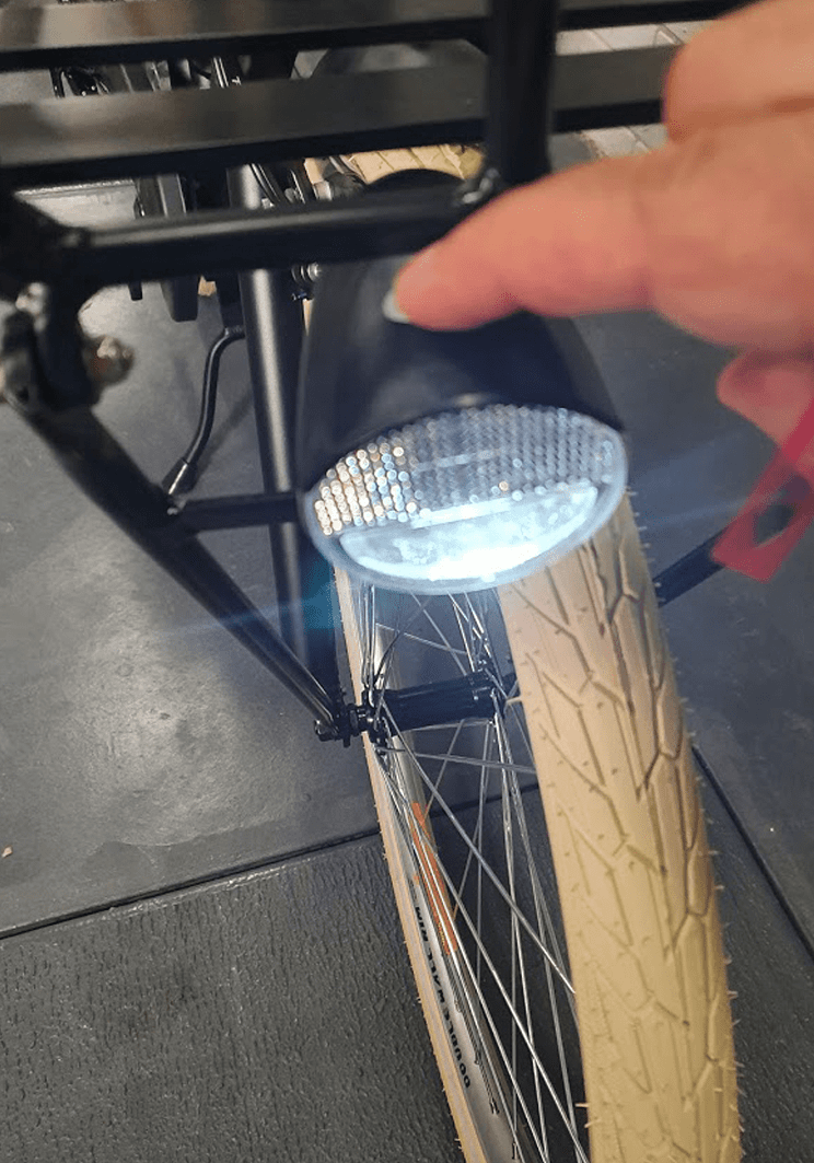
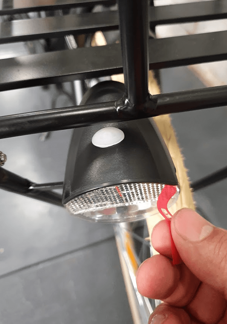
STEP 2
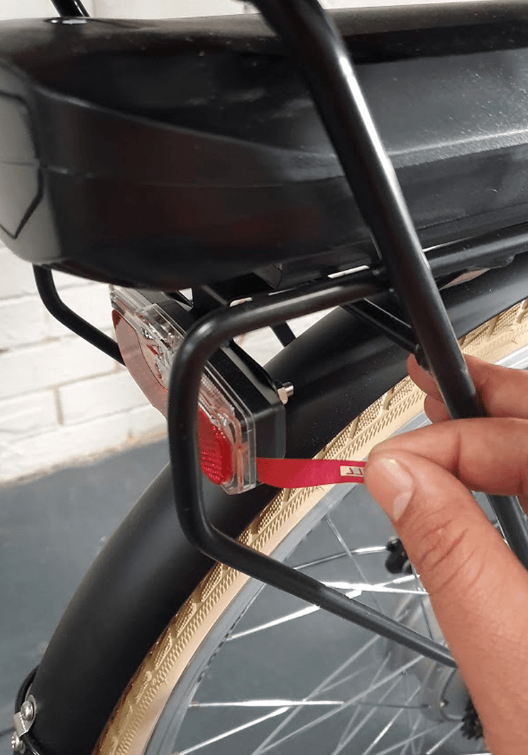
Then remove the plastic seal from the front and rear lights
STEP 3
Then press and hold the power button until the bike’s LCD turns on photo .
Then by pressing the ‘+’ button, you can increase the pedal assist level from 1 to 6.
After setting the pedal assist level, you can start riding the bike.
It is suggested to always start your ride at pedal assist level 1 and then gradually increase it, if needed.
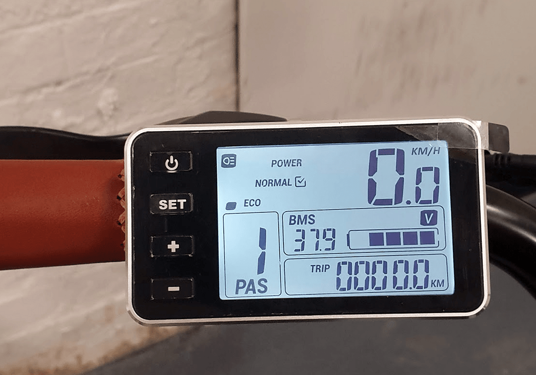
CHANGING THE BIKE POWER MODE
The bike has three power modes (eco, normal & power). The “power” mode offers the maximum power while the “eco” mode offers the least power but the max range and the “normal” mode offers a balance between power and range. By default the bike is on “normal” mode, however if needed you can change the default mode. In order to do so, please turn on the bike, hold the “set” button for 3 seconds until “0” is shown in the bottom left corner of the LCD.
Press the “+” and “-” to change between the three power modes. Then hold the “set” button for another 3 seconds until the LCD saves the setting and exists the configuration mode. Please turn off and then on the LCD and ensure the bike stays in the mode you desire.
CHANGING THE MAX SPEED
Please hold the set button for 3 seconds until “0” is shown on the bottom left side of the LCD. Then, press set button again for another 2 times until 0 changes to 2. Now you can see the bike’s current speed limit in the middle of the LCD (25 km / h by default). Now by pressing + or – you can change the speed limit. Then press and hold the set button again until the LCD saves the changes and goes back to the normal operation mode.
UNLOCKING THE THROTTLE
Please note the bike’s throttle max speed has been limited to 6km/h to be compliant with Australian standards. However, you can unlock the limit only if you intend to use the bike for off-road use only by the following steps:
While the bike panel is off, twist the throttle to the max and pull and hold one brake lever
While the throttle is twisted to the max and one brake lever is pulled, turn on and then off the bike’s panel three times.
Now release the throttle and brake one more time Turn on the panel. Now the 6 km limit is removed.
You can put the throttle speed limit back, by doing the above steps one more time. Please note riding the bike with unlocked throttle on public roads is illegal, so please remember to put back the limit before riding the bike on public roads. In order to use the throttle, the bike pedal assist level should not be on zero. If the silver button on the throttle is pushed in, the throttle works from a standstill. If the button is not pushed in, you need to twist the throttle and pedal once for the throttle to kick in. It would be better to put the bike on power mode if you need more power in pedal-assist mode or throttle mode. It would be better to put the bike on power mode, if you need more power in pedal assist mode or throttle mode.
NOTE: Unlocking the throttle will put additional strain on the motor if used as the primary source of propulsion. This needs to be taken into consideration and used with care so as not to damage the electrical components from overuse.