DiroDi Rover Plus Assembly Manual
CHAPTER 1: OVERVIEW
IMPORTANT NOTE REGARDING THE 750W DIRODI ROVER PLUS
750W DiroDi Rover PLUS is locked to 250W of power and 25 km / h speed out of the box. For off-road use, you can change the power to 500W (by changing the bike's mode from Eco to Normal) or to 750W (by changing the bike's mode from Eco to Power). You can also change the maximum speed for off-road use. Please refer to step 12 of the assembly instructions for more details.
IMPORTANT NOTE REGARDING THE DIRODI ROVER PLUS - FRONT WHEEL INSTALLATION
Installation for the front wheel is again explained later in the article - however it is important to be known that the instinctive 6mm side bolts of the wheel axle are not the primary securing nuts. They are in fact the adjacent 4x silver bolts, front facing on the bottom of the fork which securely clamp down the wheel for a service life of 6 months between checking (how tight: 12nm~). 6mm side bolts should be not overtight (8nm~) but need to be tightened before the silver adjacent bolts.
IMPORTANT NOTE REGARDING THE BATTERY SWITCH
There is an on/off switch on the battery. After daily use, please turn the switch off. To prevent the bike system from always being in Standby Mode, switching the battery off at it's switch helps avoid component degredation.
HOW TO USE THIS MANUAL
This manual contains several chapters, and each chapter contains several steps. Each step has a descriptive paragraph and some photos/videos. This manual mainly explains the assembly instructions. Therefore, please also read the other manual that comes with the bike, which includes information regarding the operation, maintenance, safety measures, etc.
IMPORTANT: For the assembly steps, please first read a step and view all the related photos/videos completely before proceeding with performing the step. If you face any difficulties during the assembly, please contact us via the website's live chat. If there are any mistakes in the manual or any information that should be added or revised for a better assembly experience, please let us know via the live chat.
TOOLS REQUIRED
- 1x 8mm wrench
- 1x 10mm wrench
- 1x 15mm wrench
- 1x Adjustable wrench
- 1x 3mm Allen key
- 1x 4mm Allen key
- 1x 5mm Allen key
- 1x 6mm Allen key
- 1x screwdriver
- 1x Scissor

CHAPTER 2: OPENING THE BOX
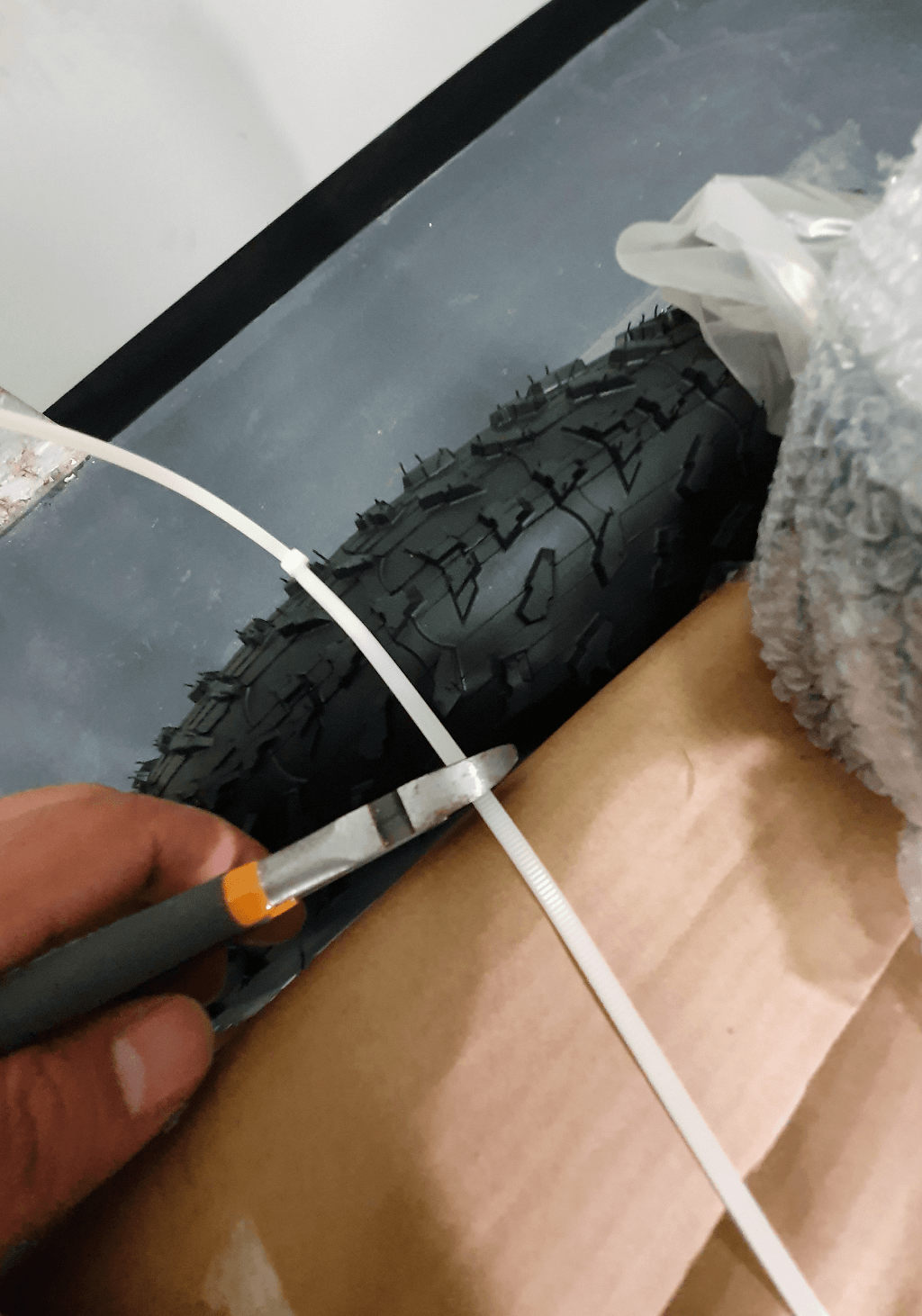
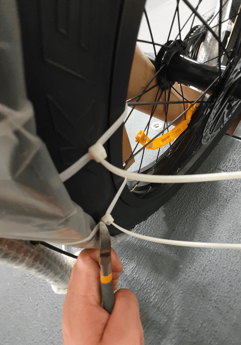
STEP 1
Cut the plastic straps off the box.


STEP 2
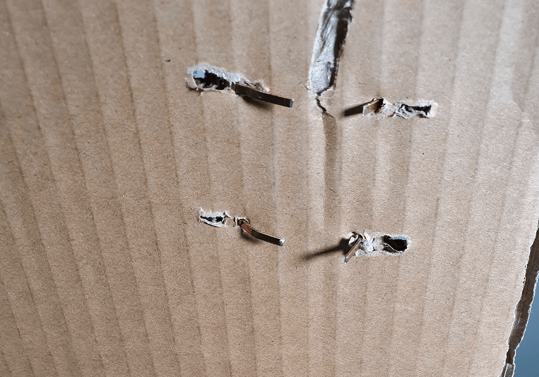
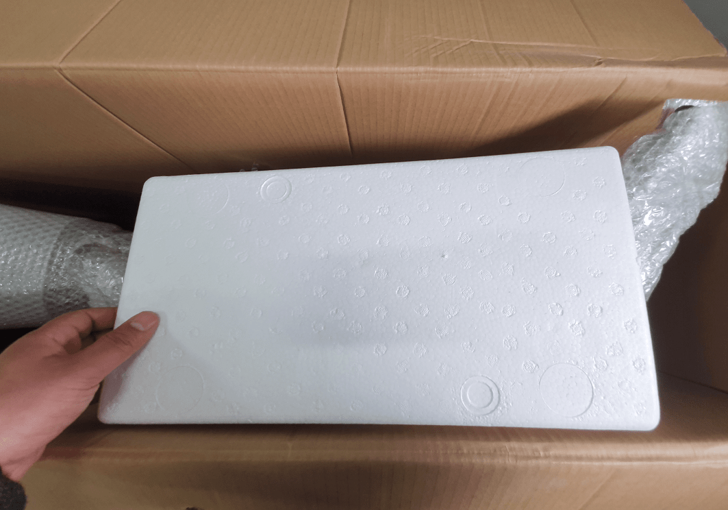
Open the carton flaps and take care so that the staples do not cut you. Remove the protective foam, cardboard, and the small accessories box.

STEP 3
Lay the carton on the floor and then remove the bike from the carton (preferably with someone's help). It is preferable to place a mat in front of the carton to prevent the bike frame from getting scratched. Then, position the bike upright.
IMPORTANT: Please note that the bike is not stable in a standing position until the front wheel is assembled. Please lean it against a wall or have someone hold the bike until the front wheel assembly step is completed (when you will be able to put the bike on the kickstand).
CHAPTER 3: REMOVING PROTECTIVE MATERIAL
STEP 1
Remove all protective material from the bike.
IMPORTANT: Please take care so that the bike frame does not get scratched.
STEP 2
Remove plastic protectors from both sides of the front wheel.
STEP 3
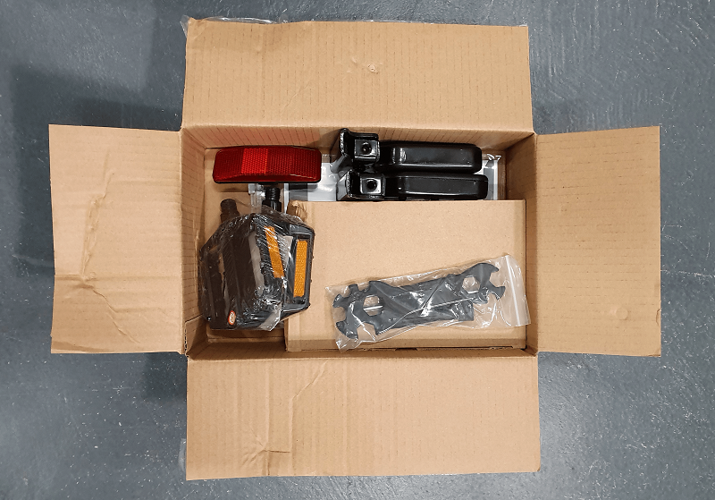
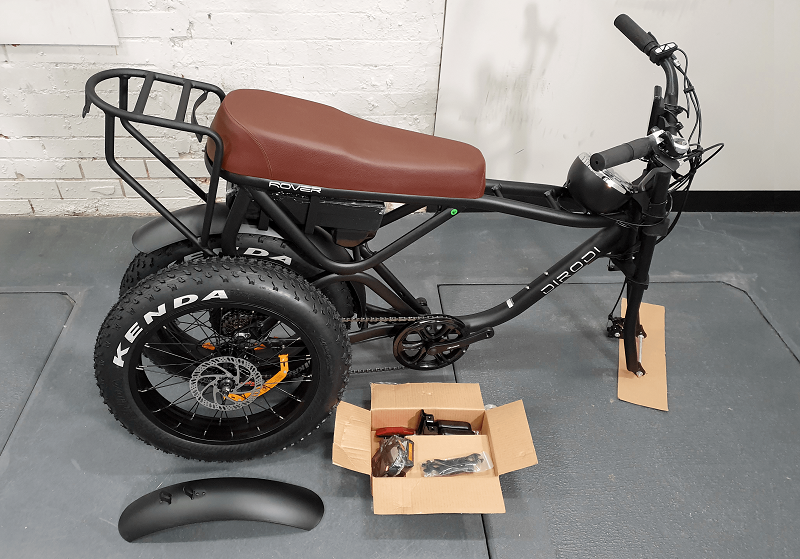
Open the accessories box, which includes the adapter, basic assembly tools, pedals, rear footrests, bike manual and LCD manual. After all protective materials are removed, your bike should look the same as the photo below.
Note: Rover Generation 3 and above don't come with a reflector as it is installed on the battery.
CHAPTER 5: PUTTING THE BIKE UPSIDE DOWN
CHAPTER 6: ASSEMBLING THE FRONT WHEEL
CHAPTER 7: ADJUSTING THE HYDRAULIC BRAKES
If you still have difficulties adjusting the brakes, please refer to the video below, which is more comprehensive.
CHAPTER 8: ASSEMBLING THE PEDALS
IMPORTANT: Ensure that both pedals are fully tightened. If they are not installed correctly, they may fall off and damage the crank thread. This can pose a significant risk while riding. Please note that such damage is not covered under warranty, so please be cautious.
CHAPTER 9: ASSEMBLING THE FRONT MUDGUARD
CHAPTER 10: INSTALLING THE LEFT FOOT PEG
CHAPTER 11: PUTTING THE BIKE BACK ON IT'S WHEELS
CHAPTER 12: INSTALLING THE FRONT LIGHT
CHAPTER 13: PUMPING THE TIRES
STEP 1
Pump the front and rear tires. The tire pressure should be within the range specified on the tire.
IMPORTANT: While pumping the tires, stop a few times to ensure that the tire bead has been properly seated all the way around the rim. If the bead starts moving up anywhere, deflate a bit, squeeze and push the bead to get it even all around, and continue inflating. If any part of the tube comes out of the rim during tire inflation, it could lead to a tube burst. In a properly seated tire, the bead line, which is the thin line moulded low on each sidewall, will be just above the rim all the way around on both sides.

