DiroDi Rover Standard Assembly Manual
CHAPTER 1: OVERVIEW
IMPORTANT NOTE REGARDING THE 750W DIRODI ROVER
750W DiroDi Rover is locked to 250W of power and 25 km / h speed out of the box. For off-road use, you can change the power to 500W (by changing the bike's mode from Echo to Normal) or to 750W (by changing the bike's mode from Echo to Power). You can also change the maximum speed for off-road use. Please refer to step 12 of the assembly instructions for more details
IMPORTANT NOTE REGARDING THE BATTERY SWITCH
There is an on/off switch on the battery. After daily use, please turn the switch off. To prevent the bike system from always being in Standby Mode, switching the battery off at it's switch helps avoid component degredation.
HOW TO USE THIS MANUAL
This manual contains several chapters, and each chapter contains several steps. Each step has a descriptive paragraph and some photos/videos. This manual mainly explains the assembly instructions. Therefore, please also read the other manual that comes with the bike, which includes information regarding the operation, maintenance, safety measures, etc.
IMPORTANT: For the assembly steps, please first completely read a step and view all the related photos/videos and then proceed with performing the step. If you face any difficulties during the assembly, please contact us via the website’s live chat. If there are any mistakes in the manual or any information that should be added or revised for a better assembly experience, please let us know via the live chat.
TOOLS REQUIRED
- 1x 8mm wrench
- 1x 10mm wrench
- 1x 15mm wrench
- 1x Adjustable wrench
- 1x 3mm Allen key
- 1x 4mm Allen key
- 1x 5mm Allen key
- 1x 6mm Allen key
- 1x screwdriver
- 1x Scissor

CHAPTER 2: OPENING THE BOX
STEP 1
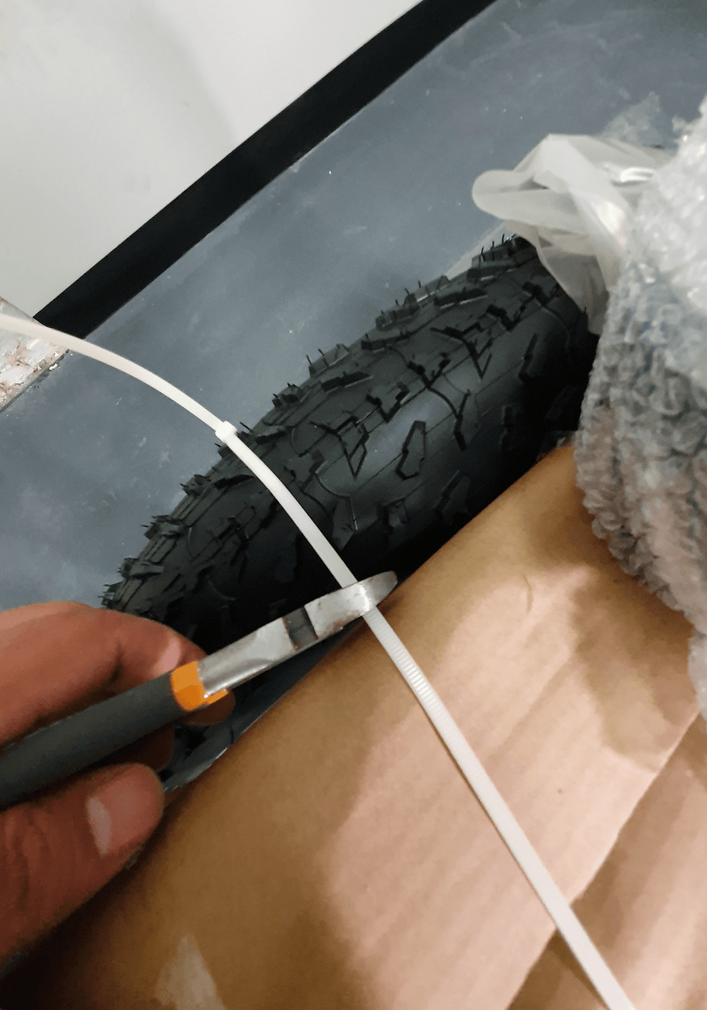
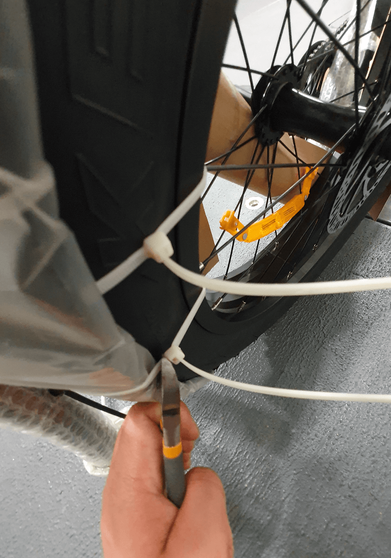
Cut the plastic straps off the box.


STEP 2
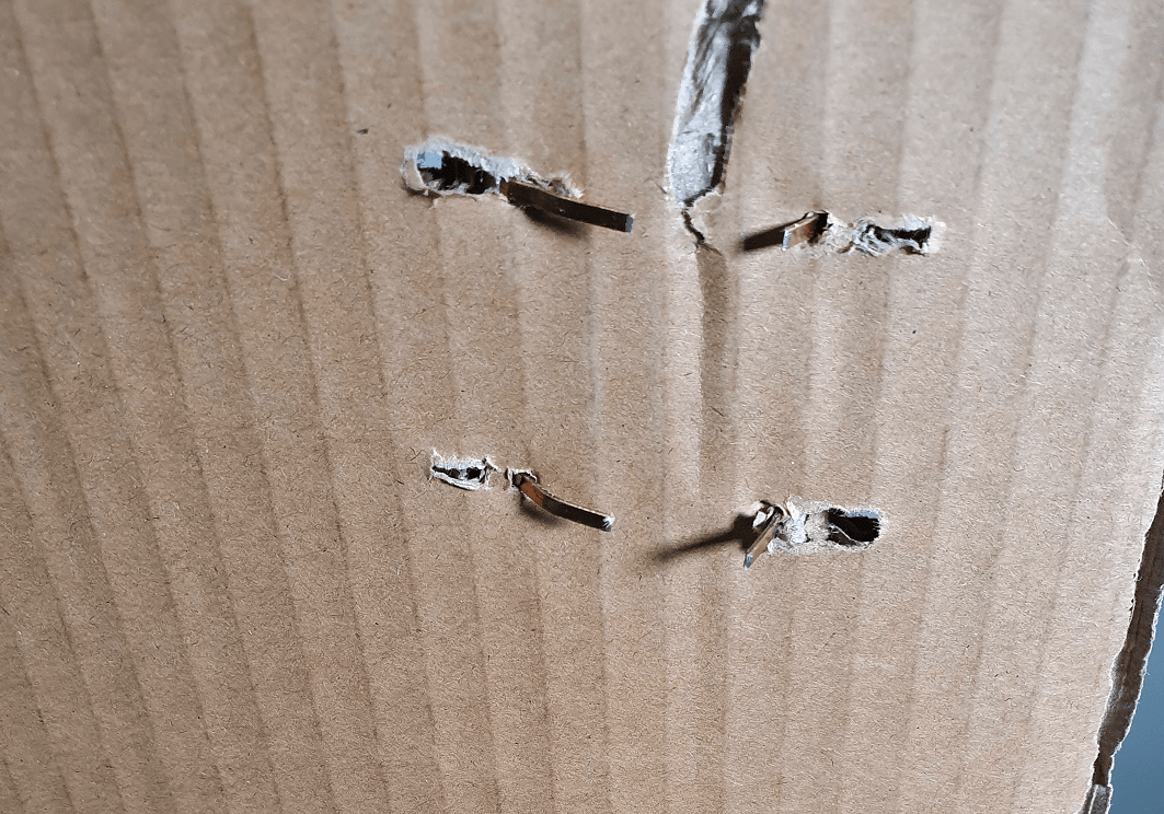
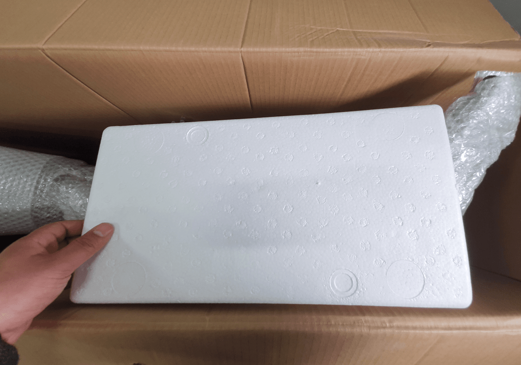
Open the carton flaps and take care so that the staples do not cut you. Remove the protective foam, cardboard, and the small accessories box.

STEP 3
Lay the carton on the floor and then remove the bike from the carton (preferably with someone's help). It is preferable to place a mat in front of the carton to prevent the bike frame from getting scratched. Then, position the bike upright.
IMPORTANT: Please note that the bike will not be stable in a standing position until the front wheel is assembled. Please lean it against a wall or have someone hold the bike until the front wheel assembly step is completed (when you will be able to put the bike on the kickstand).
CHAPTER 3: REMOVING PROTECTIVE MATERIAL
STEP 1
Remove all protective material from the bike
IMPORTANT: Please take care so that the bike frame does not get scratched.
STEP 2
Remove plastic protectors from both sides of the front wheel.

STEP 3
Remove the steel fork protector from the front fork by loosening the nuts on both sides.
STEP 4
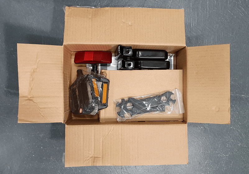
Open the accessories box, which includes the adapter, basic assembly tools, pedals, rear footrests, bike manual and LCD manual. After all protective materials are removed, your bike should look the same as the photo below.
Note: Rover Generation 3 and above don't come with a reflector as it is installed on the battery.

CHAPTER 4: FRONT LIGHT ASSEMBLY
STEP 1
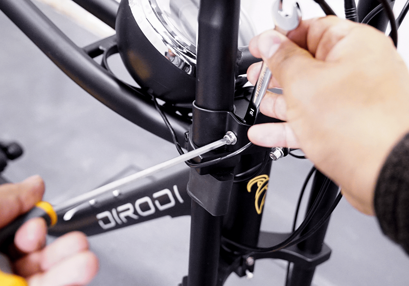
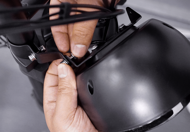
Loosen the front light's right bracket by holding the nut with a wrench and turning the bolt by an Allen key anti-clockwise. Do the same on the left bracket.
STEP 2
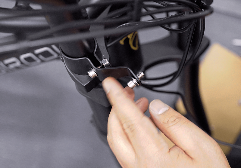
Remove the nut and the washer located in the front of the right bracket. The bracket should look the same as the second photo below, after the washer and the nut is removed. Do the same on the left bracket.
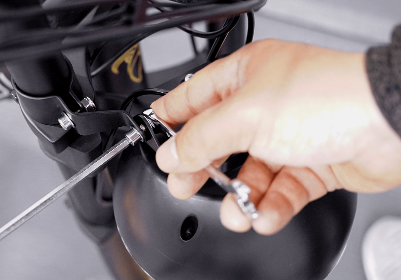
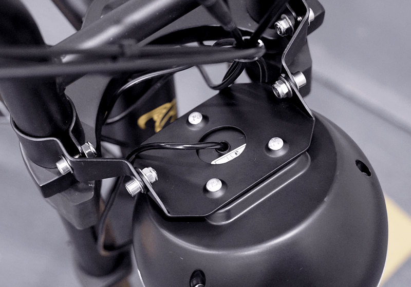
STEP 3
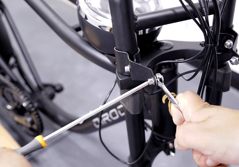
Install the front light as shown in the photos below by using a wrench and an Allen key. After the front light is tightened to the brackets, please adjust the angle of the light so it faces forward.
NOTE: If the front light's cable is passed in between the front forks (and not from one side of the fork), then you need to unplug the front light cable from the connection point, assemble the light and then reconnect the connection. Before reconnecting the light cable ensure the two sides of the connection are aligned otherwise, the pins might get bent.

CHAPTER 5: FRONT MUDGUARD ASSEMBLY
STEP 1
Remove the 4 bolts from the bike’s forks and install the mudguard in such a way that the shorter side of the mudguard is in front of the forks and the longer side is behind the forks. Now tighten the 4 bolts (2 on each side).

CHAPTER 6: FRONT WHEEL ASSEMBLY
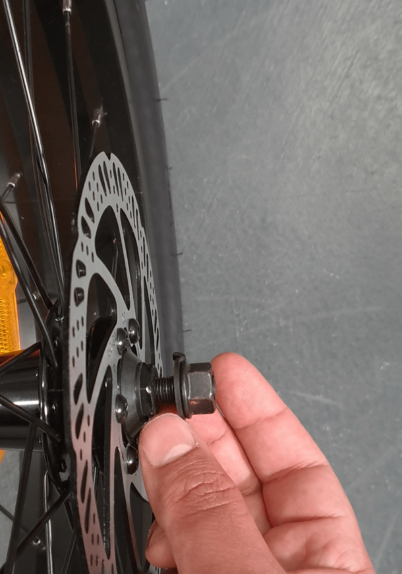
STEP 1
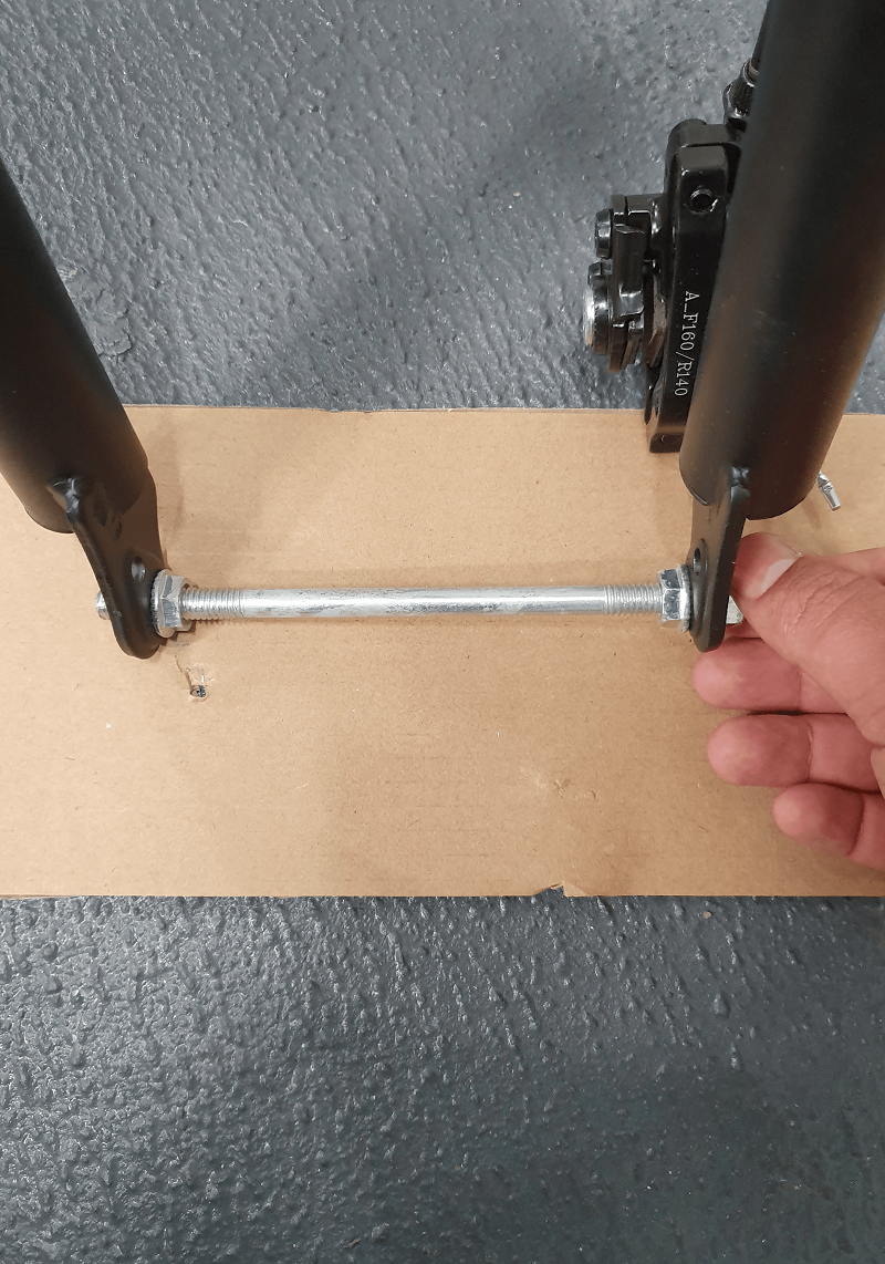
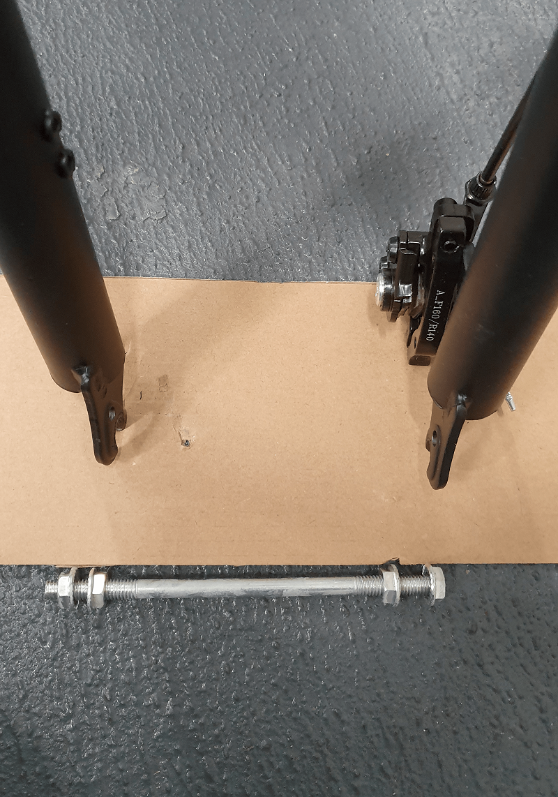
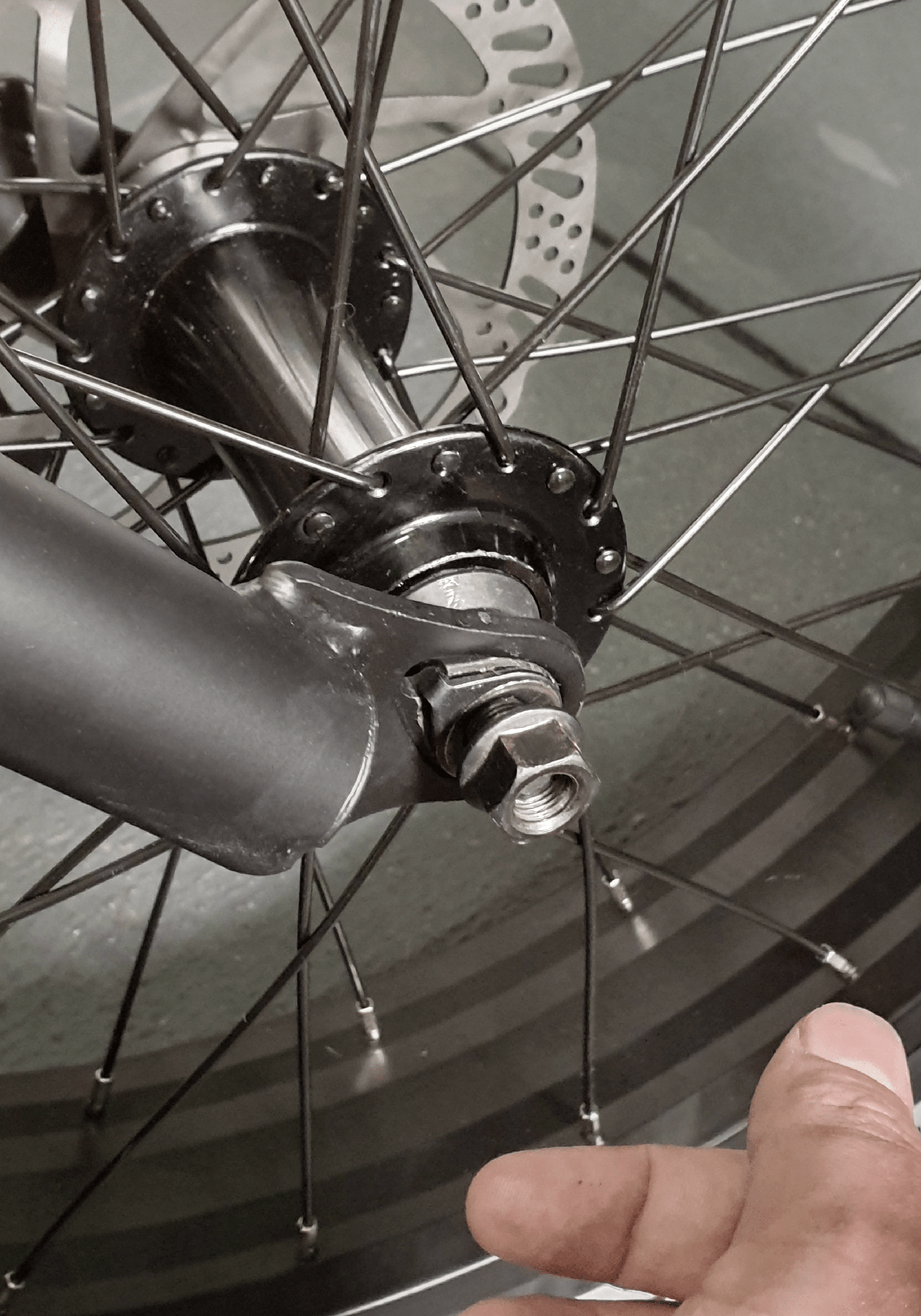
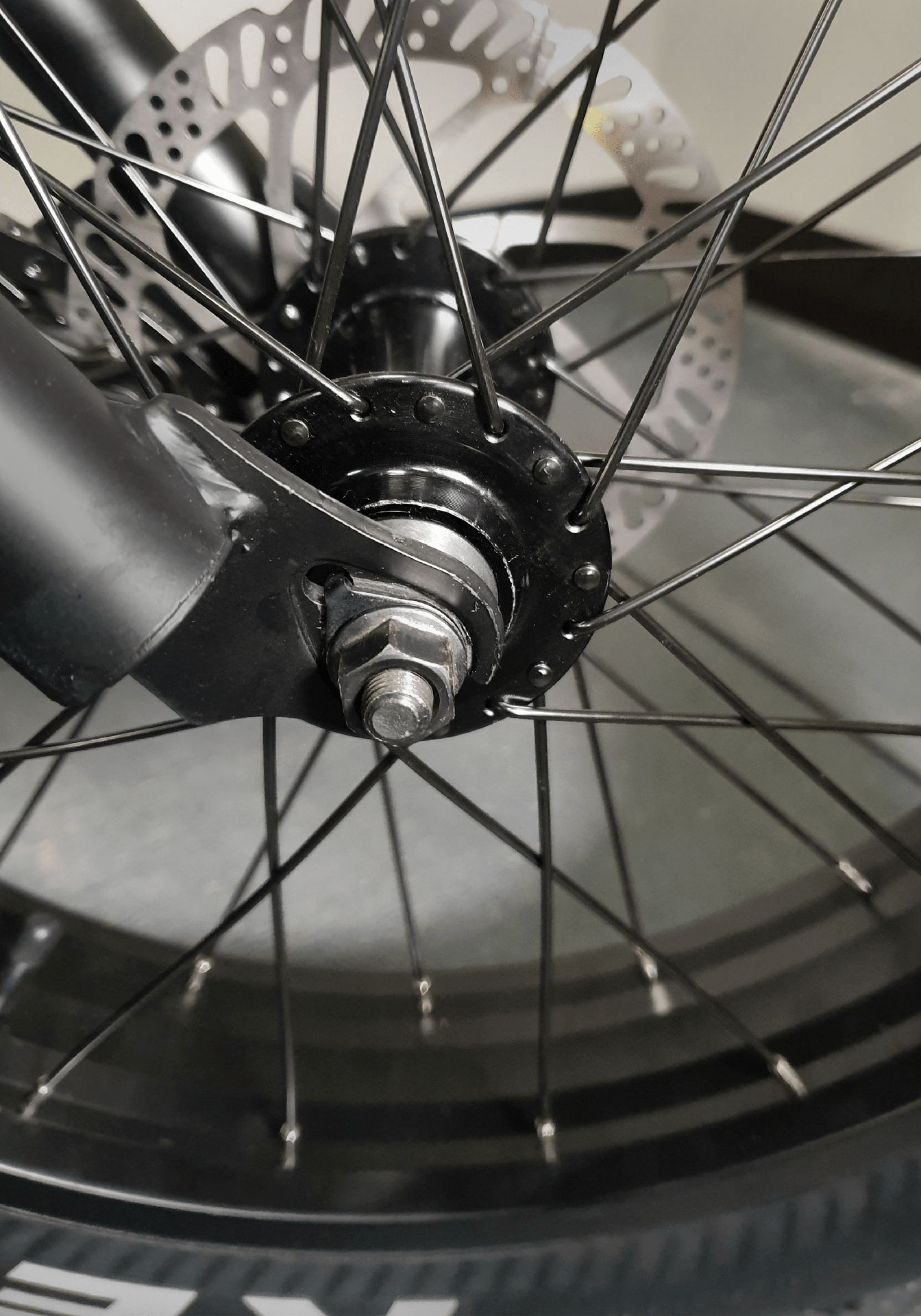
Remove the washer and the nut as shown in the photos below from both sides of the front wheel hub.
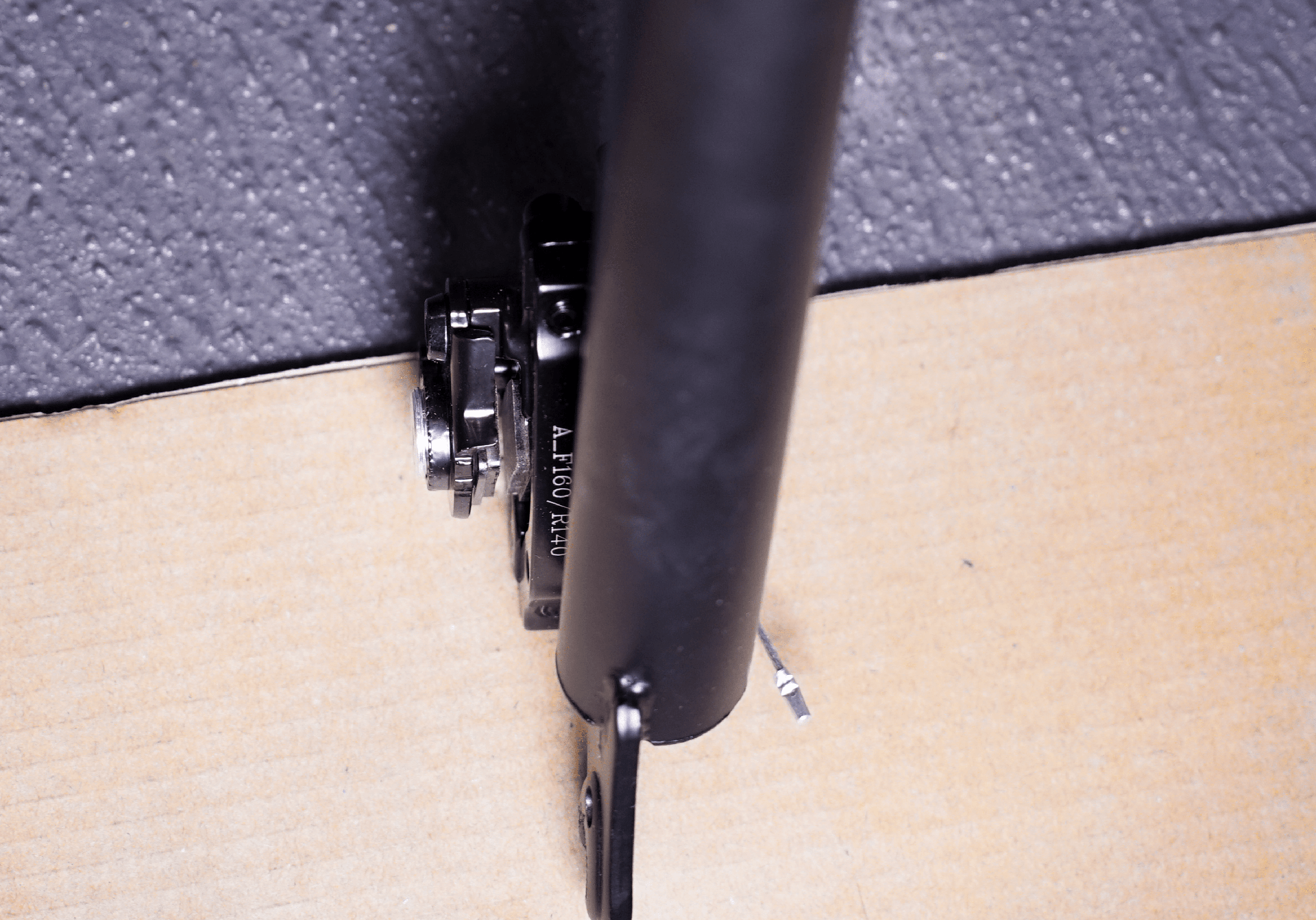
STEP 2
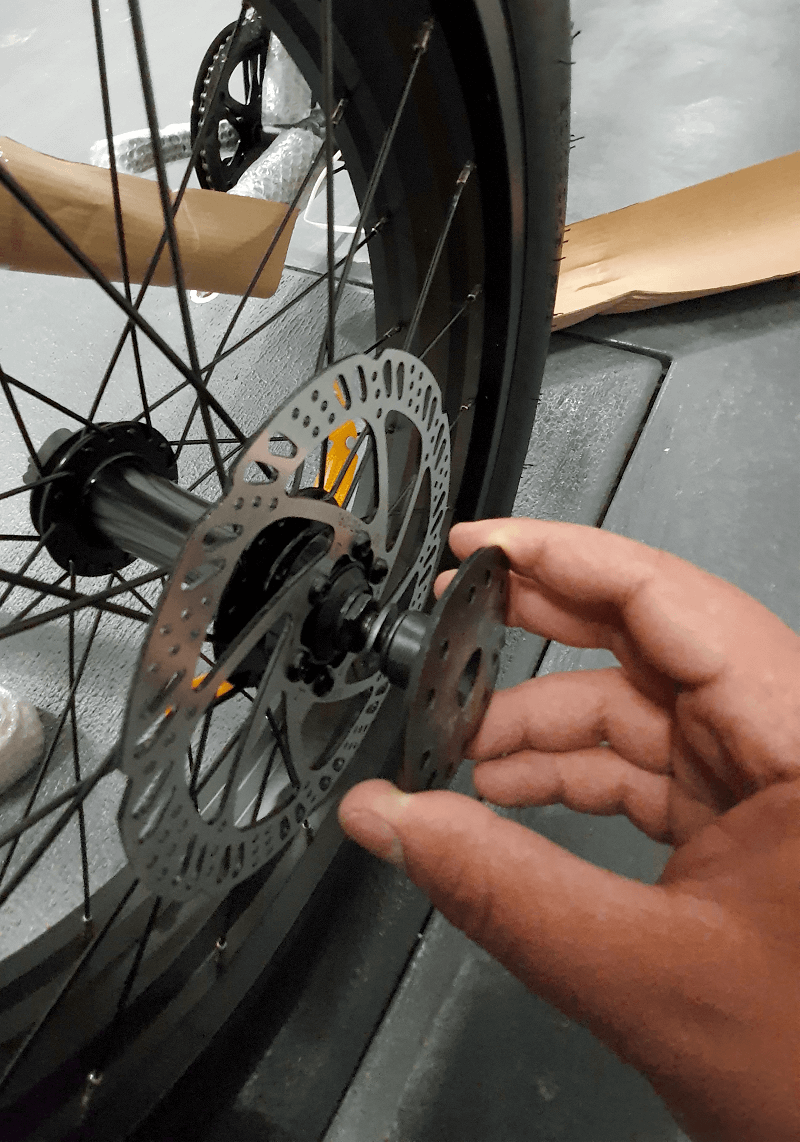
Please note the disk rotor should go in the tiny space between the brake pads.
IMPORTANT: Please note this step is very sensitive and if done wrong, the brake pads or the disk rotor can be damaged.

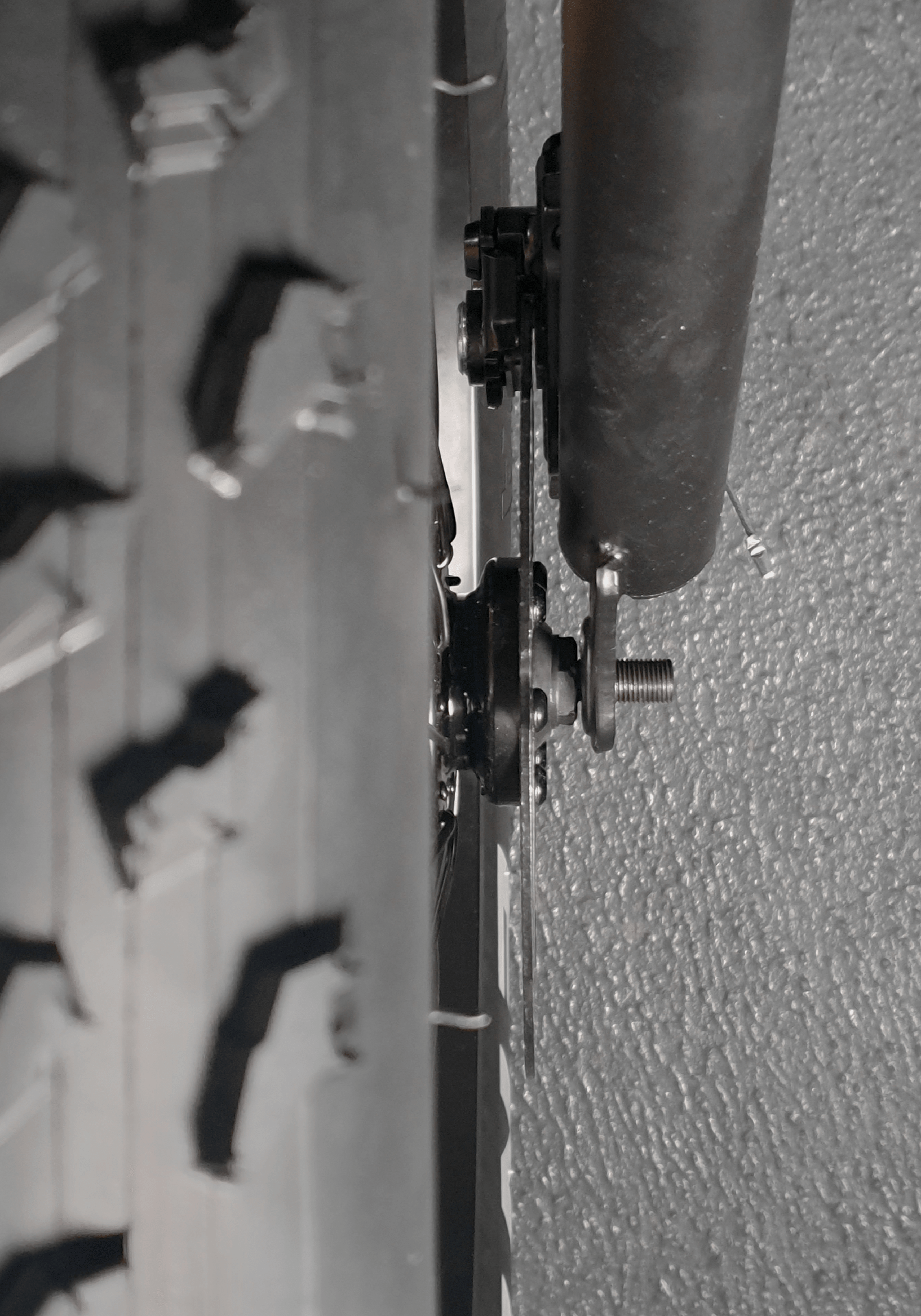
STEP 3
Ask someone to hold the front tyre (photo 4) and then lift the bike and carefully lower the forks until the disk brake rotor is inserted between the brake pads and the axel fits nicely in the front forks.
STEP 4
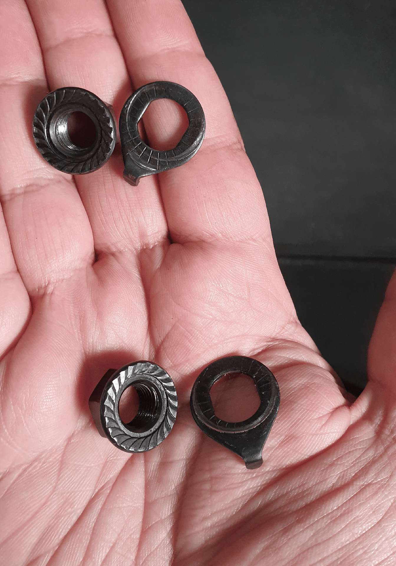
Insert the locking washer to the axel on the right and ensure it is locked just as shown in photo below.
STEP 5
Please note the washer tap should be inserted in the hole on the fork so that it locks. Then hand tighten the nut. Do the same steps on the left.
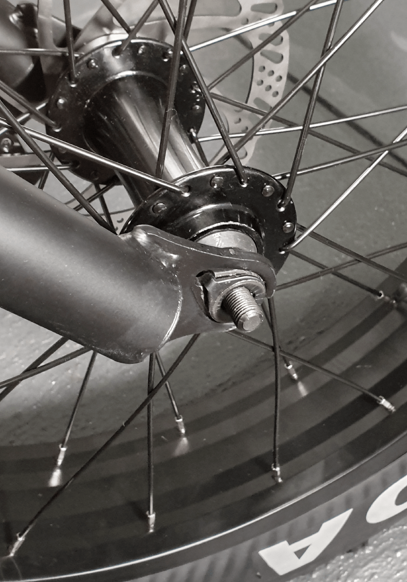
STEP 6
Now tighten the nuts on both sides as shown in photos below. Please note in this step, you should tighten the nut on one side a bit and then tighten the other nut a bit and repeat the process until both nuts are fully tightened. While tightening the nuts, you should try to keep the tyre centred between the forks. If after the nuts are tightened, the tyre is leaning to one side more, please loosen both nuts and try again.


IMPORTANT: In this step the bike should not be on the kickstand as centring the tyre between the forks while the bike is on kickstand is difficult.
IMPORTANT: In this step the bike should be on the wheels (not upside down on the handlebars). The weight of the bike helps the tyre’s axel be fully inserted into the fork dropouts and makes the tyre be centred between the forks easier.
CHAPTER 7: PEDALS ASSEMBLY
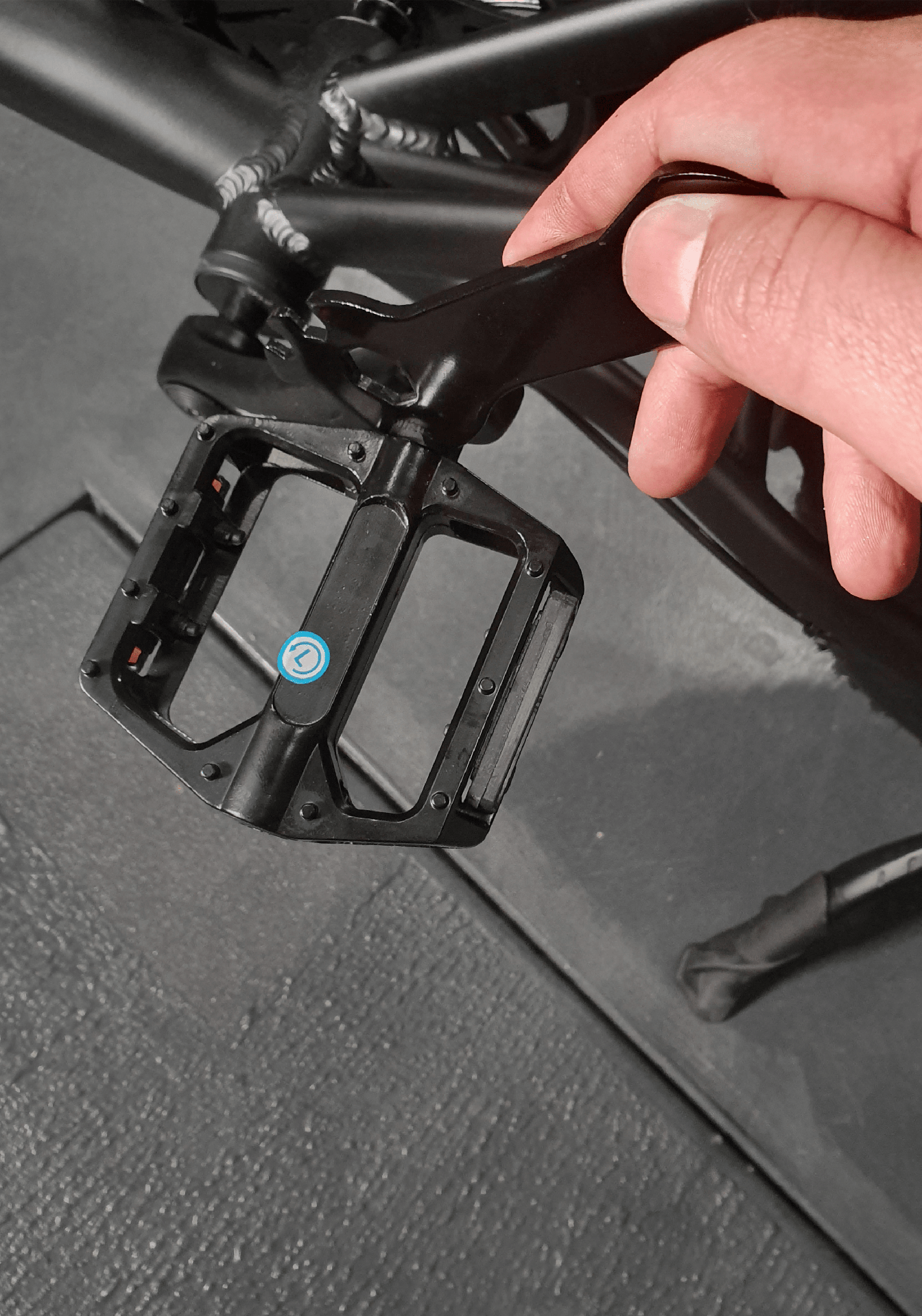
STEP 1
IMPORTANT: This step is sensitive and if done wrong, the threads on the pedal or the crank might get stripped. You should tighten the pedals by hand as much as possible and then fully tighten them by using a wrench.
IMPORTANT: Please ensure the pedals are fully tightened otherwise pedals can gradually get loosen and strip the crank arm threads.
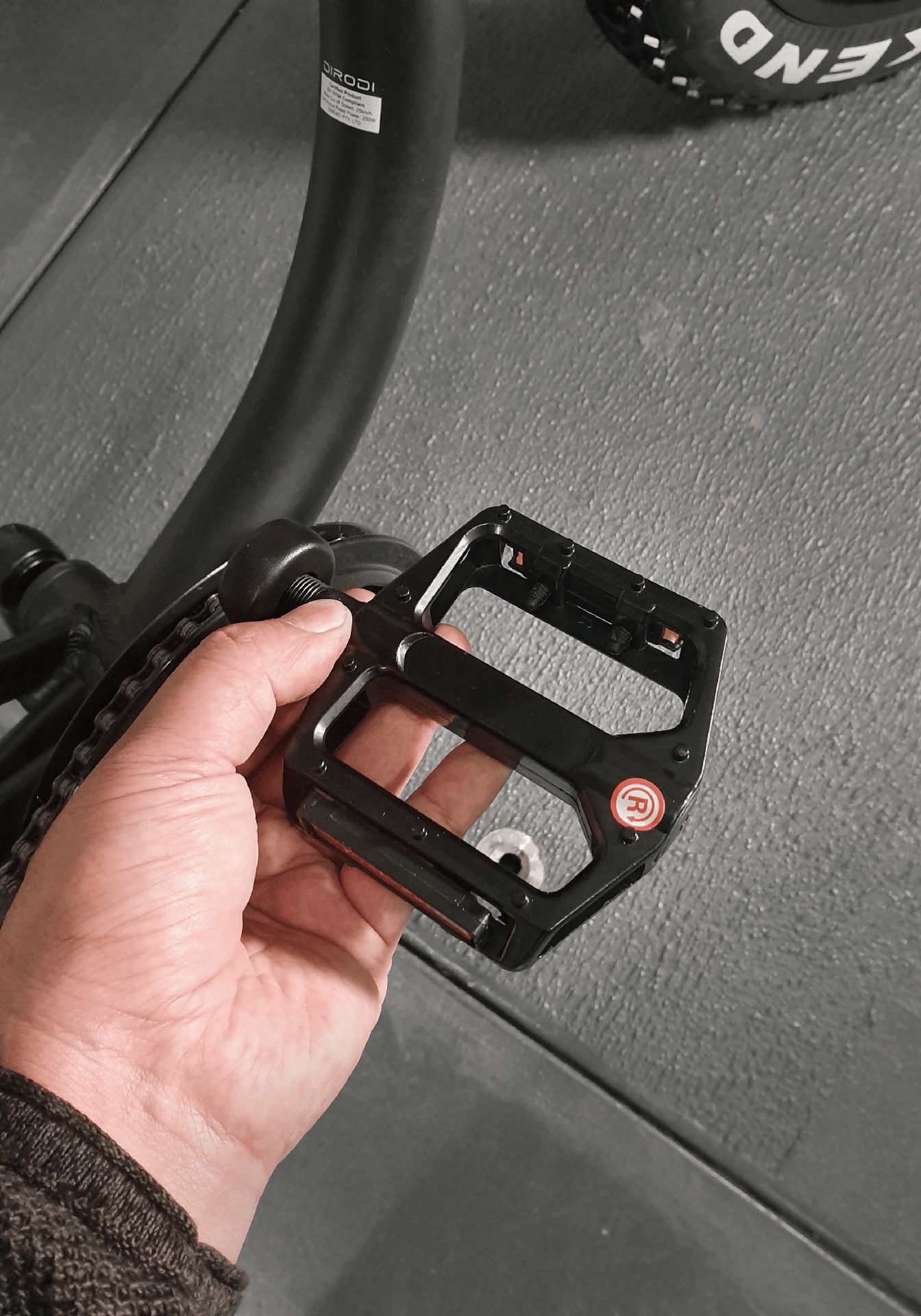
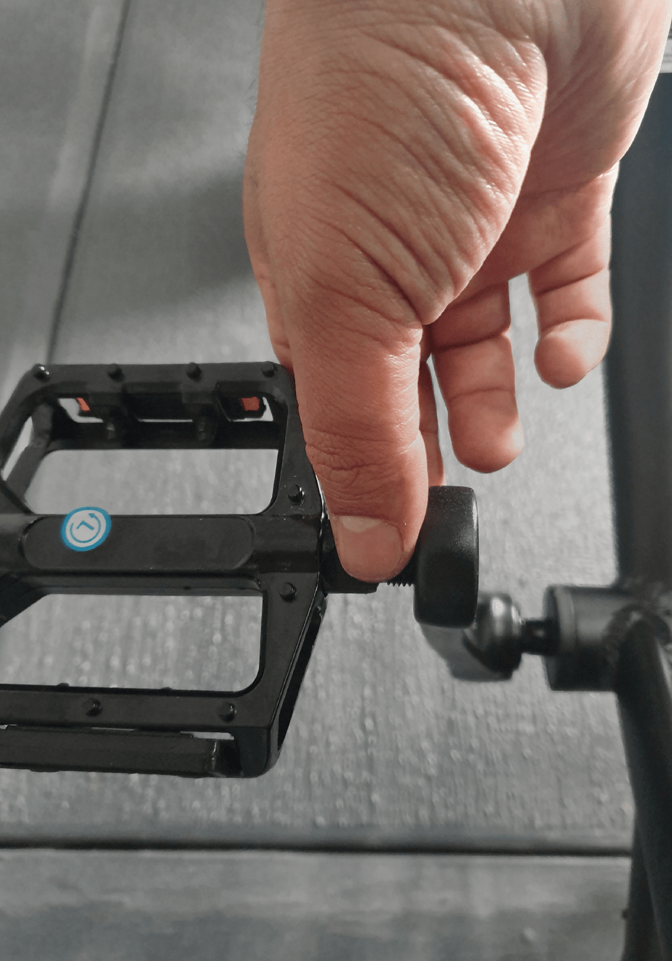
Tighten the right pedal to the right crank by turning it clock wise by hand (photo 1). You should be able to tighten the pedal almost all the way down by your hand.
STEP 2
Tighten the left pedal to the left crank by turning it anti-clockwise by hand. You should be able to tighten the pedal almost all the way down by your hand.
STEP 3
Tighten both pedals fully by using a wrench. Please ensure both pedals are fully tightened.
IMPORTANT: Ensure both pedals are fully tightened. If they are not installed correctly they will fall off and damage the crank thread which can be extremely dangerous while riding. This is something that is not covered under warranty so please take care.
CHAPTER 8: FOOTREST ASSEMBLY
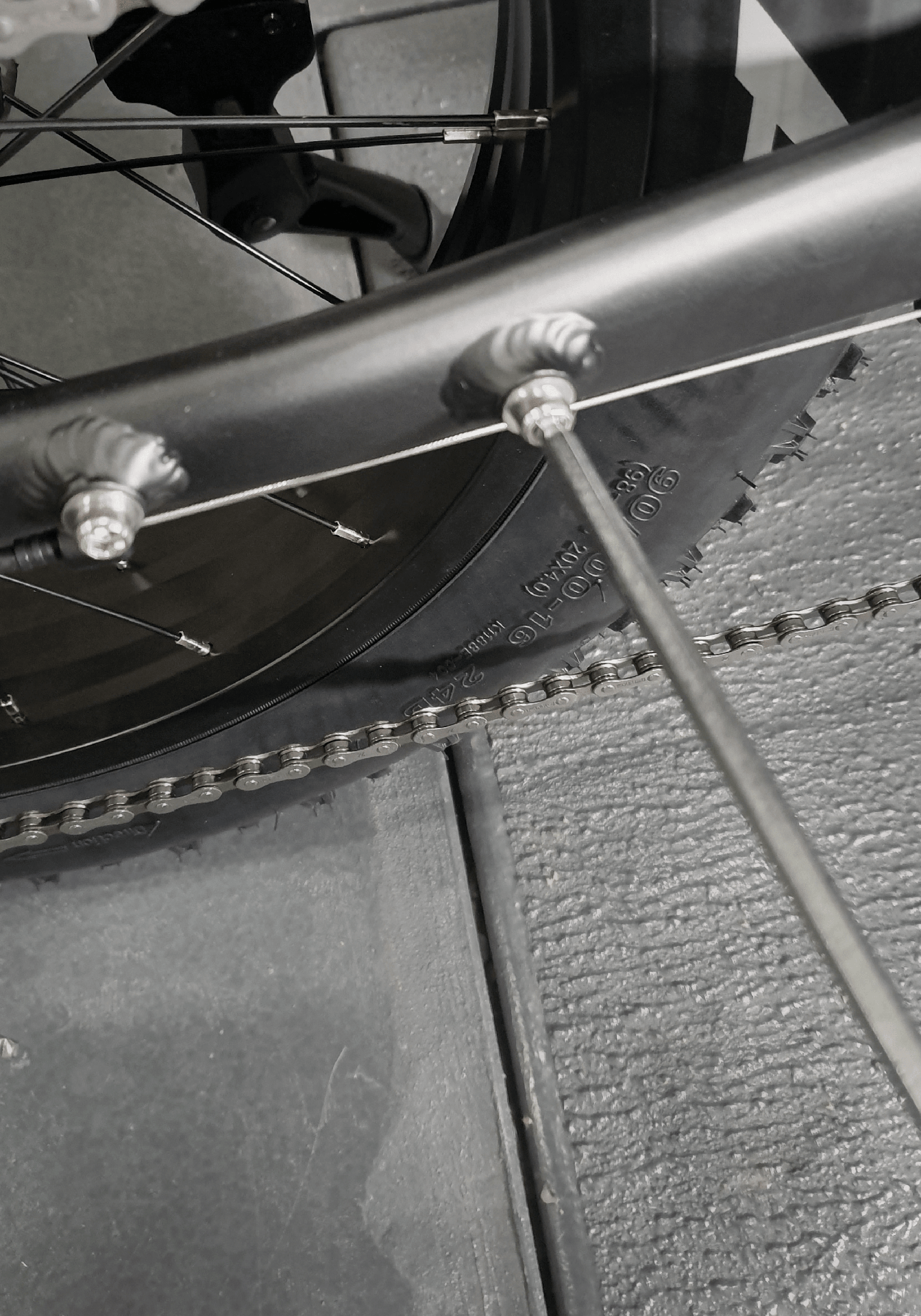
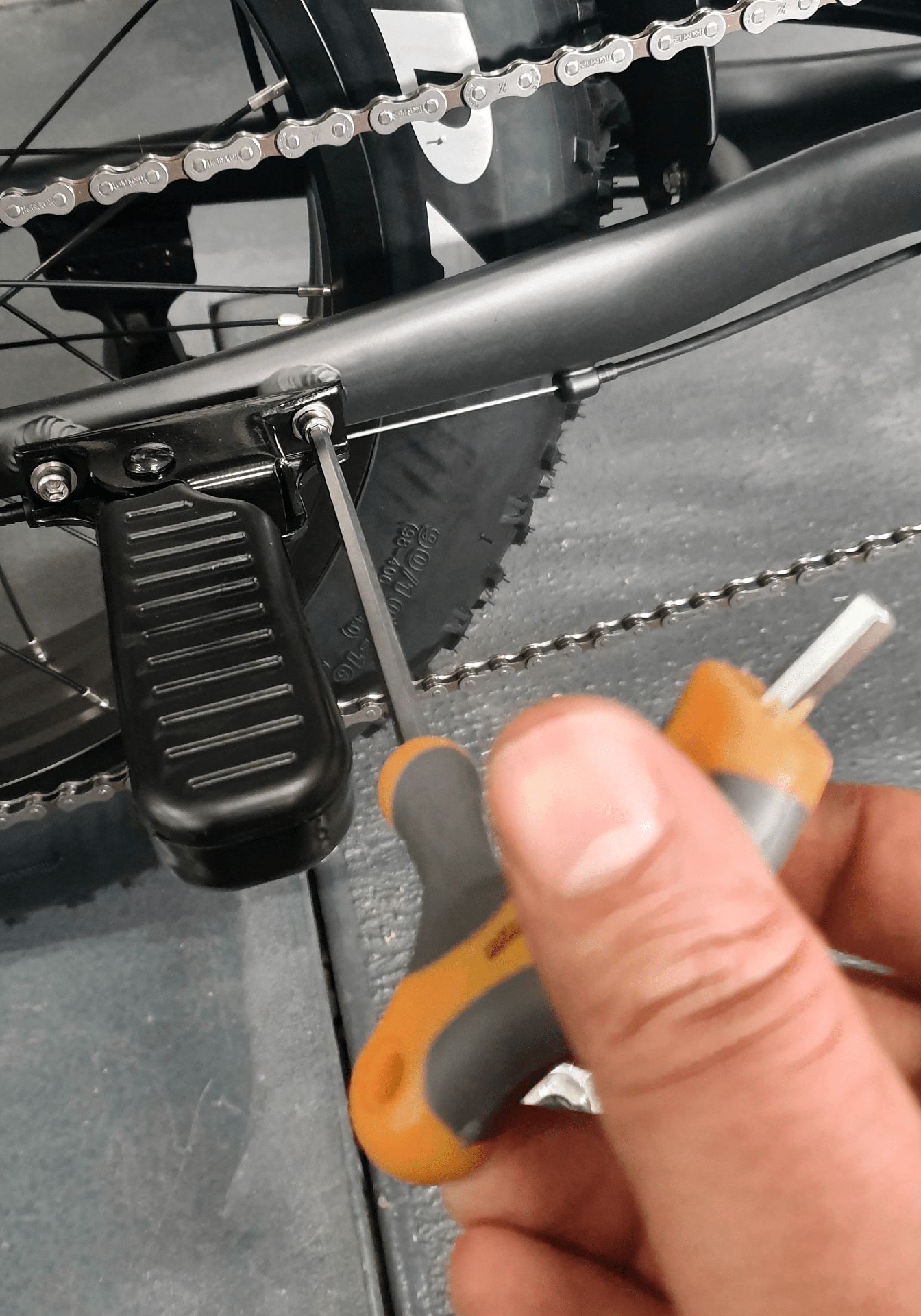
STEP 1
Remove the 2 bolts shown in the first photo below. Install the right footrest in such a way that the curved side of the footrest is facing forward so that it folds backward (photo 2). Do the same on the other side.
CHAPTER 9: PUMPING THE TYRES
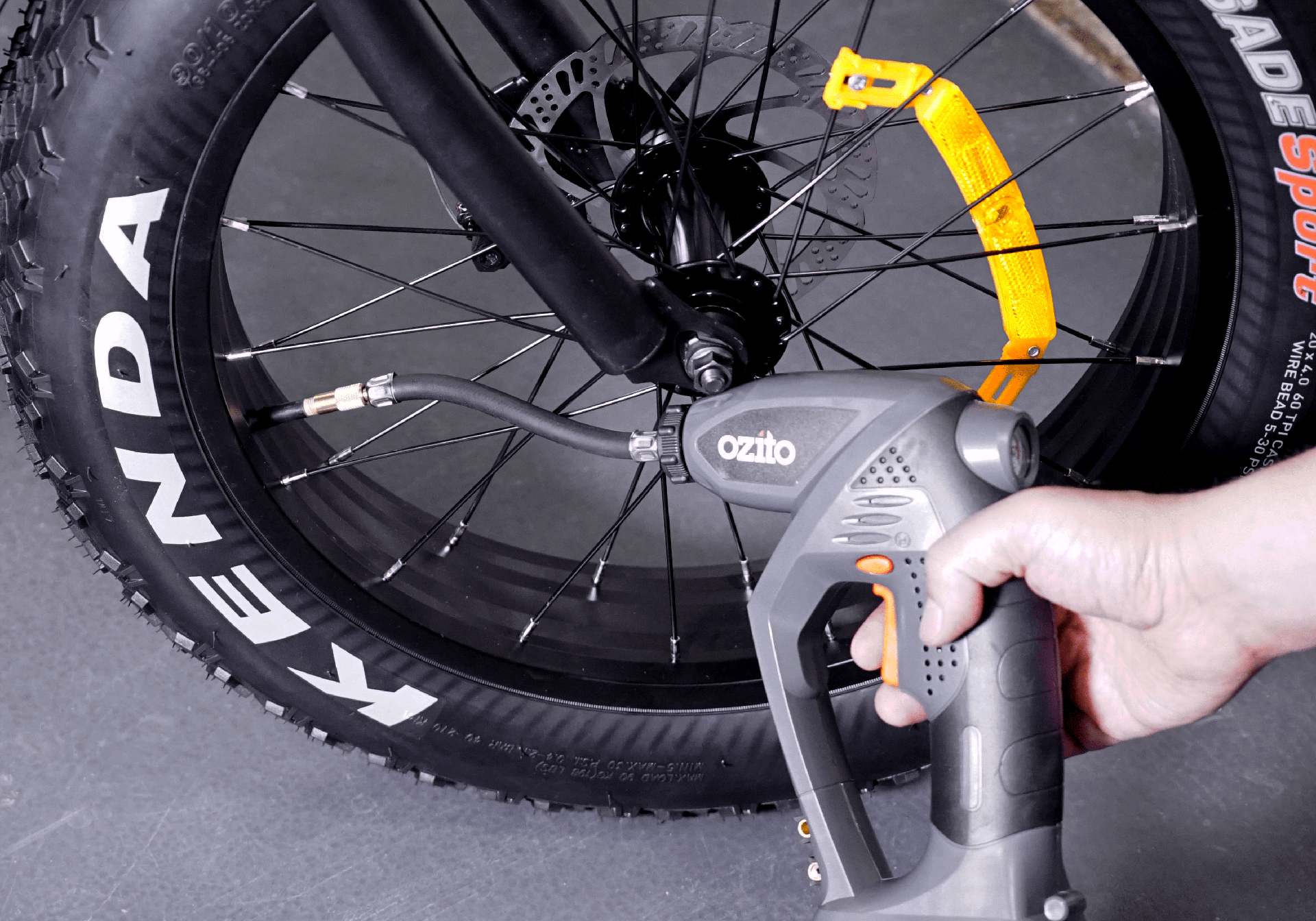
STEP 1
Pump front and rear tyres. Tyre pressure should be in the range specified on the tyre.
IMPORTANT: While pumping the tyres, stop a few times and ensure the tyre bead has been seated properly all the way around the rim. If the bead starts moving up anywhere, deflate a bit, squeeze and push the bead to get it even all around and continue inflating. If any part of the tube comes out of the rim during tyre inflation, it could lead to a burst tube. In a properly seated tyre, the bead line — the thin line moulded low on each sidewall — will be just above the rim all the way around on both sides.

CHAPTER 10: DISK BRAKE ADJUSTMENT
STEP 1
IMPORTANT: Before proceeding with this step, if there is a disk brake pad spacer between the pads (photo below), please remove it. You can dispose of it.
The rear brake is adjusted in the factory. For front brake adjustment, please refer to the below link:
FOR MECHANICAL BRAKES
https://www.youtube.com/watch?v=NmqGeLNcVIg
FOR HYDRAULIC BRAKES
Please refer to the below video for hydraulic disk brakes adjustment (Please note the bolts that should be loosened as part of the process are highlighted in photo below)
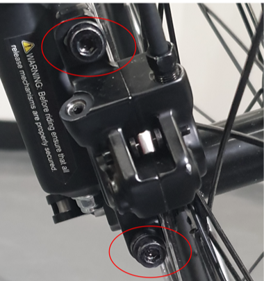
https://www.youtube.com/watch?v=uk_nC9anQcM
CHAPTER 11: REAR DERAILLEUR ADJUSTMENT
STEP 1
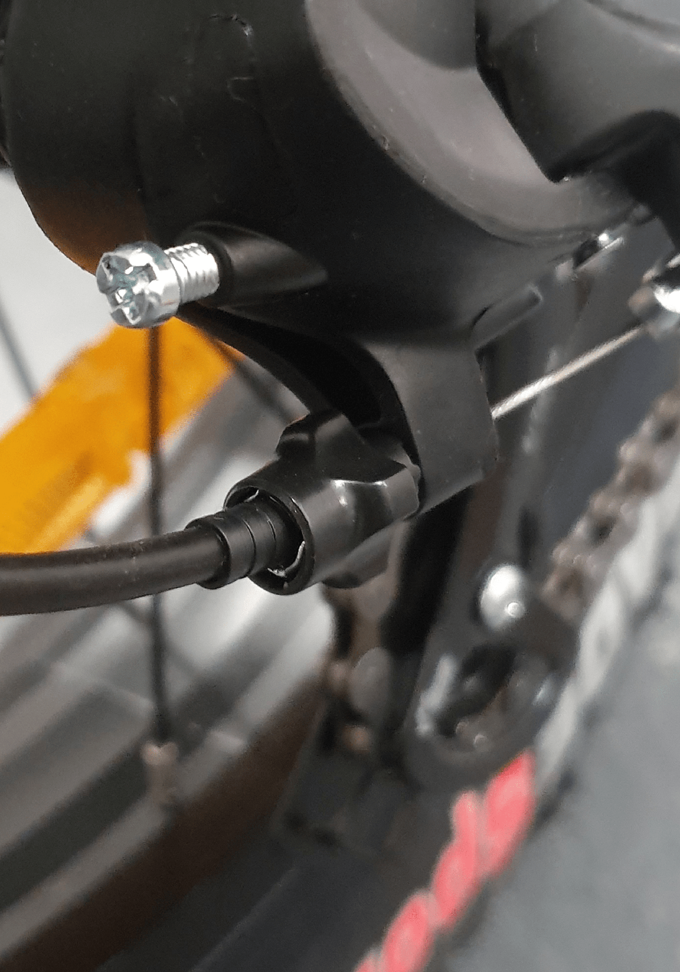
The rear derailleur has been adjusted in the factory but due to parts movement during shipment, slight re-adjustments might be necessary. Derailleur adjustment is done by barrel adjuster and “H” and “L” screws as shown in photos below.
The process is explained in the video below in detail:
https://www.youtube.com/watch?v=UkZxPIZ1ngY
NOTE: Please note as the derailleur is already adjusted in the factory, any issues in changing gear between gear #2 to #6, should be easily solved by turning the barrel adjuster in the right direction (As per instructions in the video above). After the gears are smoothly changed between gear #2 to #6, please test gear #1 (the largest cog) and #7 (the smallest cog). If you have any issues on gear #1, you need to adjust the “L” screw and if you have any issues on gear #7, you need to adjust the “H” screw as explained in the video above.

CHAPTER 12: OPERATING THE BIKE
IMPORTANT: The laws around the use of electric bikes on public lands, roads and areas vary from state to state. We recommend you always check your local council and road traffic laws prior to using a bike to ensure you are aware of any restrictions that may affect the use of motorised vehicles. Always use appropriate protective riding equipment such as an approved helmet and suitable clothing.
TURNING ON AND RIDING THE BIKE
Press and hold the power button until the bike’s LCD turns on (photo 1). Then by pressing the ‘+’ button, you can increase the pedal assist level from 1 to 6. After setting the pedal assist level, you can start riding the bike. It is suggested to always start your ride at pedal assist level 1 and then gradually increase it, if needed.

CHANGING THE BIKE POWER MODE
The bike has three power modes (eco, normal & power). The “power” mode offers the maximum power while the “eco” mode offers the least power but the max range and the “normal” mode offers a balance between power and range. By default the bike is on “normal” mode, however if needed you can change the default mode. In order to do so, please turn on the bike, hold the “set” button for 3 seconds until “0” is shown on the top right corner of the LCD.
Then press “+” one time so that the mode changes to “power”, or press “-” one time if you want to change to “eco” mode. Then you need to hold the “set” button for another 3 seconds until the LCD saves the setting and exists the configuration mode. Please turn off and then on the LCD and ensure the bike stays in the mode you desire.
UNLOCKING THE THROTTLE
Please note the bike’s throttle max speed has been limited to 6km/h to be compliant with Australian standards. However, you can unlock the limit only if you intend to use the bike for off-road use only by the following steps:
While the bike panel is off, twist the throttle to the max and pull and hold one brake lever
While the throttle is twisted to the max and one brake lever is pulled, turn on and then off the bike’s panel three times.
Now release the throttle and brake one more time Turn on the panel. Now the 6 km limit is removed.
You can put the throttle speed limit back, by doing the above steps one more time. Please note riding the bike with unlocked throttle on public roads is illegal, so please remember to put back the limit before riding the bike on public roads. In order to use the throttle, the bike pedal assist level should not be on zero. If the silver button on the throttle is pushed in, the throttle works from a standstill. If the button is not pushed in, you need to twist the throttle and pedal once for the throttle to kick in. It would be better to put the bike on power mode if you need more power in pedal-assist mode or throttle mode. It would be better to put the bike on power mode, if you need more power in pedal assist mode or throttle mode.
NOTE: Unlocking the throttle will put additional strain on the motor if used as the primary source of propulsion. This needs to be taken into consideration and used with care so as not to damage the electrical components from overuse. Additional care should be taken if using the 250W model.
CHANGING THE MAX SPEED
Please hold the set button for 3 seconds until “0” is shown on the bottom left side of the LCD. Then, press set button again for another 2 times until 0 changes to 2. Now you can see the bike’s current speed limit in the middle of the LCD (25 km / h by default). Now by pressing + or – you can change the speed limit. Then press and hold the set button again until the LCD saves the changes and goes back to the normal operation mode.
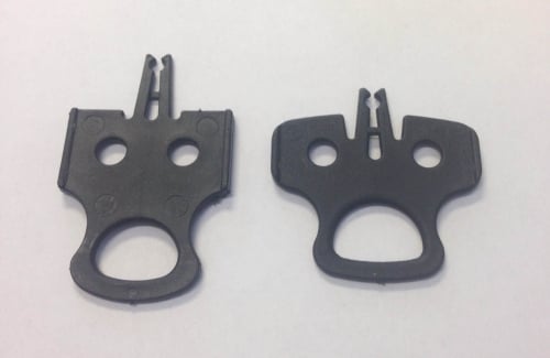
THROTTLE BUTTON - GREY
Throttle button toggle in is 'throttle always on mode'. Throttle button toggle out is 'throttle pedal follow mode'.
WALK ASSIST FEATURE
This feature is designed to allow the motor to push the bike along while you walk beside it, up a parking ramp for example. In order to activate the walk-assist feature, please turn on the bike and press and hold the “-” button.
ACTIVATE USB CHARGING OUTLET FROM KEYPAD
Hold + & SET for 3 seconds, notice USB Symbol appear on display.
Plugging a USB cable in will now charge a device using the eBike battery.
Passcode Instructions
Turn on the bike.
Press and hold the '+' and 'SET' buttons for 5 seconds until the light turns on.
Press and hold the plus and minus buttons until the display changes
Input your password by changing the digits with '+' and '-', use 'SET' to jump to the next digit.
Hold 'SET' to save
*Now the bike password is activated and will need to be input every time you turn the bike on*
To change the password turn on the bike, hold down the 'SET' and '-' buttons, input the original password then input the new password, hold 'SET' to save
To deactivate the password feature press and hold the '+' and 'SET' buttons for five seconds while the bike is on and unlocked
If you want a passcode and throttle unlock, best to proceed with the throttle unlock first.
IMPORTANT NOTE REGARDING YOUR BIKE SECURITY
Before using the bike, please record the bike's serial number in case your bike gets stolen. We don't keep track of each bike's serial number for each order. You will need your bike's serial number to lodge a police report if it is stolen.
We strongly recommend using a premium lock to secure the bike. We suggest using ABUS or Kryptonite U locks. We suggest investing around 5% of the bike's price to buy a lock.
In addition to using a U lock, the following methods can be used to further reduce the risk of theft:
- Installing an apple air tag under the bike's seat. In this case, the bike can be tracked if it is stolen.
- Using a bike disk brake lock.
- Installing a bike alarm system. The siren will sound if the bike moves.
- Insuring your e-bike. By doing a google search, you can find companies that offer e-bike insurance in Australia.
In our experience, bike parts theft (e.g. saddle, tyres, LCD, etc.) happens very rarely as these parts are not usually compatible with other brand bikes and therefore do not have a reselling value. Therefore, it's better to keep your focus on securing the bike frame rather than on different parts.
Unfortunately, electric bike theft is common in Australia. Even by using the best lock and security systems, your bike is not going to become 100% theft-proof. Therefore, it's always better to avoid parking your bike in public places for an extended period of time or overnight.
BIKE SERIAL NUMBER
Please record the serial number of your bike. For Rover, it is located on the head tube, printed and starting with PSG...
Dirodi does not record the serial numbers. They are designed to be used as the owner's reference in the event of theft to provide identification to police.