DiroDi Rover Gen 5/6 Plus Assembly Manual
CHAPTER 1: OVERVIEW
IMPORTANT NOTE REGARDING THE 1000W DIRODI ROVER5
1000W DiroDi Rover is locked to 250W of power and 25 km/h speed out of the box. For off-road use, you can change the power to 500W (by changing the bike's mode from Eco to Normal) or to 1000W (by changing the bike's mode from Eco to Power). You can also change the maximum speed for off-road use. Please refer to step 12 of the assembly instructions for more details.
IMPORTANT NOTE REGARDING THE DIRODI ROVER PLUS - FRONT WHEEL INSTALLATION
Installation for the front wheel is again explained later in the article - however, it is important to know that the instinctive 6mm side bolts of the wheel axle are not the primary securing nuts. They are in fact the adjacent 4x silver bolts, front facing on the bottom of the fork which securely clamp down the wheel for a service life of 3 months between checking (how tight: 12nm~). 6mm side bolts should be not overtight (8nm~) but need to be tightened before the silver adjacent bolts.
IMPORTANT NOTE REGARDING THE BATTERY SWITCH
-If you choose to charge the battery while it is still inserted on the bike, then please switch the red battery switch off.
-If you choose to charge the battery outside of the bike, then the switch can be on or off.
-If you leave the battery inserted into bike, after daily use, please turn the switch off. To prevent the bike system from always being in Standby Mode, switching the battery off at it's switch helps avoid component degredation.
Throttle Unlock
Video guide - https://youtu.be/ptIROjKdPQI
Written instructions below
Please note the bike’s throttle max speed has been limited to 6km/h to be compliant with Australian standards. However, you can unlock the limit only if you intend to use the bike for off-road use only by the following steps. Riding the bike with an unlocked throttle on public roads is illegal, so please remember to put back the limit before riding the bike on public roads.
While the bike panel is off, twist the throttle to the max and pull and hold one brake lever
- While still holding the throttle and brake lever in place, turn the bike on and off three times using the control panel.
- The bike's throttle should now be unlocked and go up to the full speed of the bike.
You can put the throttle speed limit back, by doing the above steps.
- To use the throttle, the bike pedal assist level should be 1 or higher.
- If the grey button on the throttle is pushed in, this is throttle always on mode. If the button is not pushed in, you need to twist the throttle and pedal once for the throttle to kick in or it acts as a throttle safety for when the bike is stationary.
NOTE: Unlocking the throttle will put additional strain on the motor if used as the primary source of propulsion. This needs to be taken into consideration and used with care so as not to damage the electrical components from overuse. Additional care should be taken if using the 250W model.
For example if you are riding uphill with 2 people, you will not be able to climb some hills only with the throttle. This is due to maximum capability for this weight class of ebike, ebike power laws, suitable off-road specs and power rating for motor and controller designed to make the most effective product.
MODE & DRIVE MODE
1000W Model:
ECO: 250W
NOR: 500W
POW: 1000W
>MODE - Located General Settings, 2nd page
>Speed code required above 25kmh
>To attain public key, attempt to increase speed above 25kmh (General Settings) 4 digit code on screen will appear. Provide public key to Dirodi for unique speed unlock code.
250/500W Model:
P2 is only available to NSW customers. P2 is the 500w mode activation.
P1: ECO 150W, NOR 200W, POW 250W
P2: ECO 250W, NOR 350W, POW 500W
>MODE - Located General Settings, 2nd page
>Speed code required above 25kmh
>To attain public key, attempt to increase speed above 25kmh, 4 digit code on screen will appear. Provide public key to Dirodi (will be supplied upon request with public key Dirodi ticket/email)
>To allow P2 setting, Power code will be to be input (will be supplied upon request with public key Dirodi ticket/email)
Power code is unique / different from speed code
Example Public Key
Notice that public key matches last 4 digits on frame serial number


Example of codes replied from Dirodi - via website ticket, Contact Us. Please provide your sales receipt. Power code only given to NSW customers.
-Display Unlock Code used in the case that one has forgotten log in password. Acts as master code for log in password. To set up log in password, navigate to Advance Settings, Password creation.
QUICK CONTROLS
Rover Gen6.1 switch pad
See below
Rover Gen6.0 switch pad
See below


ASSEMBLY GUIDE & AFTERCARE
Please read whole manual for aftercare & warranty purposes.
DiroDi E-Bike Battery Safety & Charging Instructions
⚠
Important Safety Information
Failure to follow these guidelines may result in battery damage, fire, or injury. To reduce the risk
of injury or fire, read the user guide before using the bike or battery.
1. Use Only the Original Charger
o Always charge with the original DiroDi charger. Refer to the user manual for
charger specifications.
o Using an incorrect charger may cause battery damage or fire.
2. Charging Safety
o Always charge in a dry, ventilated area away from flammable materials.
o Do not charge overnight – unplug once fully charged.
o Do not charge in exit ways – ensure escape routes remain clear in case of
emergency.
o Never charge in extreme temperatures (below 0°C or above 40°C).
o Do not short-circuit the battery.
3. Battery Handling & Maintenance
o Store between 10°C and 25°C in a cool, dry place.
o If the battery is unused for an extended period, charge it every 90 days for 2
hours to maintain performance.
o Never leave a battery that is almost empty for an extended period of time – charge
it as soon as possible.
o Keep away from direct sunlight, heat sources, or water.
o Do not puncture, drop, or disassemble the battery.
4. Electrical Safety
o Do not modify any electrical components – modifications may cause
component damage or fire.
o If buying second-hand, refer to the manual or contact DiroDi to ensure the
battery and charger are original and the bike has not been modified. Always
request proof of purchase from the seller.
5. Fire Safety
o In case of fire, do not attempt to extinguish. Exit immediately and call 000.
6. Safe Usage
o When possible, charge before the battery level drops below 20% to extend lifespan
o Do not attempt to use a damaged or swollen battery.
o Dispose of responsibly according to local regulations—do not throw in household
waste.
HOW TO USE THIS MANUAL
This manual contains several chapters, and each chapter contains several steps. Each step has a descriptive paragraph and some photos/videos. This manual mainly explains the assembly instructions. Therefore, please also read the other manual that comes with the bike, which includes information regarding the operation, maintenance, safety measures, etc.
IMPORTANT: For the assembly steps, please first completely read a step and view all the related photos/videos and then proceed with performing the step. If you face any difficulties during the assembly, please contact us via the website’s live chat or other communication channels. If there are any mistakes in the manual or any information that should be added or revised for a better assembly experience, please let us know via the live chat.
TOOLS REQUIRED
- 1x 8mm wrench
- 1x 10mm wrench
- 1x 15mm wrench
- 1x Adjustable wrench
- 1x 3mm Allen key
- 1x 4mm Allen key
- 1x 5mm Allen key
- 1x 6mm Allen key
- 1x screwdriver
- 1x Scissor / cutter

CHAPTER 2: OPENING THE BOX
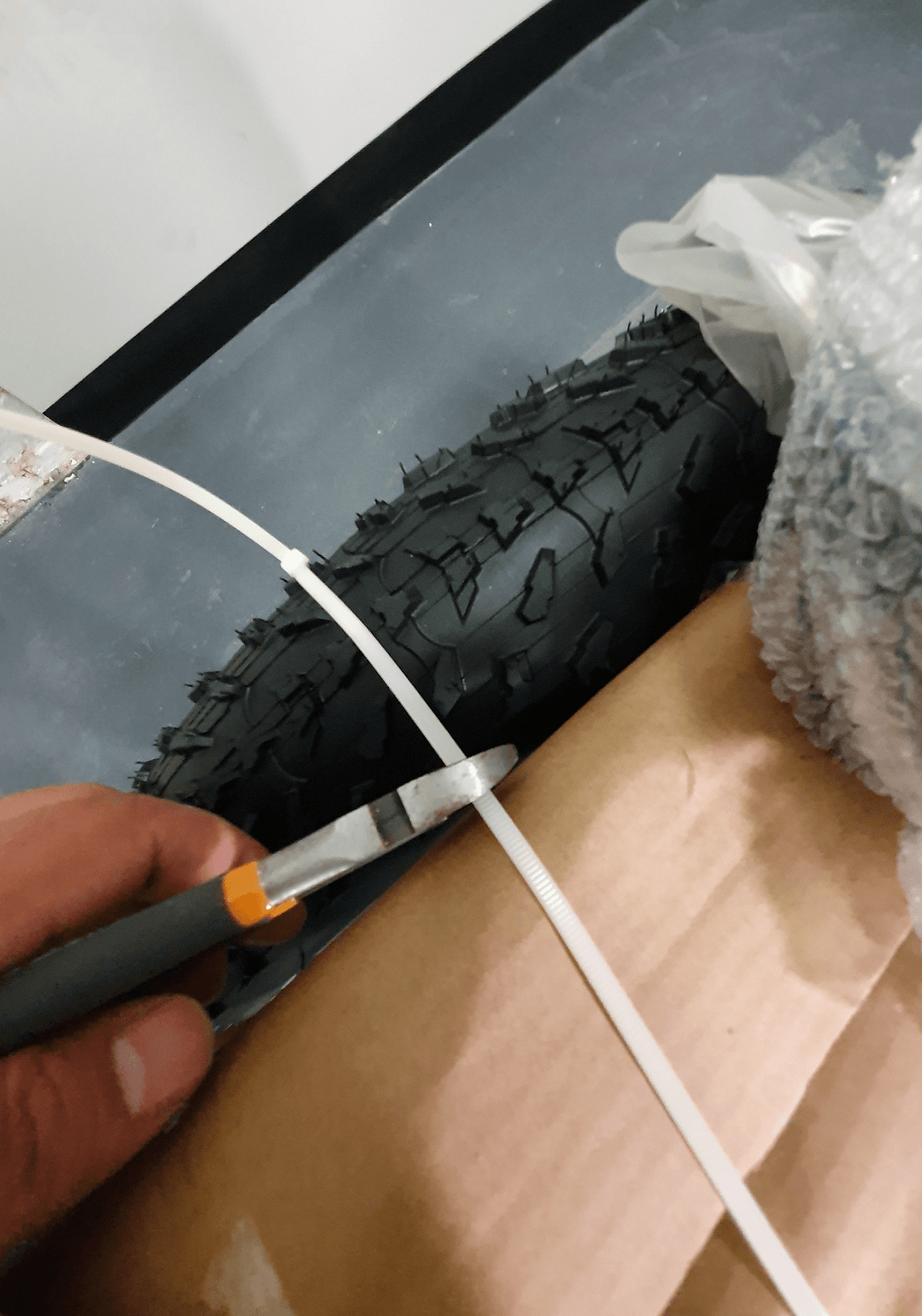
STEP 1
Cut the plastic straps off the box.


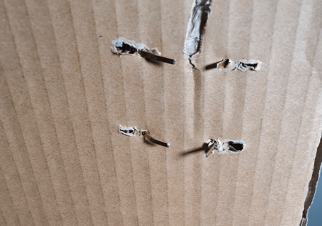
STEP 2
Open the carton flaps and take care so that the staples do not cut you. Remove the protective foam, cardboard, and the small accessories box.

STEP 3
Lay the carton on the floor and then remove the bike from the carton (preferably with someone's help). It is preferable to place a mat in front of the carton to prevent the bike frame from getting scratched. Then, position the bike upright.
IMPORTANT: Please note that the bike will not be stable in a standing position until the front wheel is assembled. Please lean it against a wall or have someone hold the bike until the front wheel assembly step is completed (when you will be able to put the bike on the kickstand).
CHAPTER 3: REMOVING PROTECTIVE MATERIAL
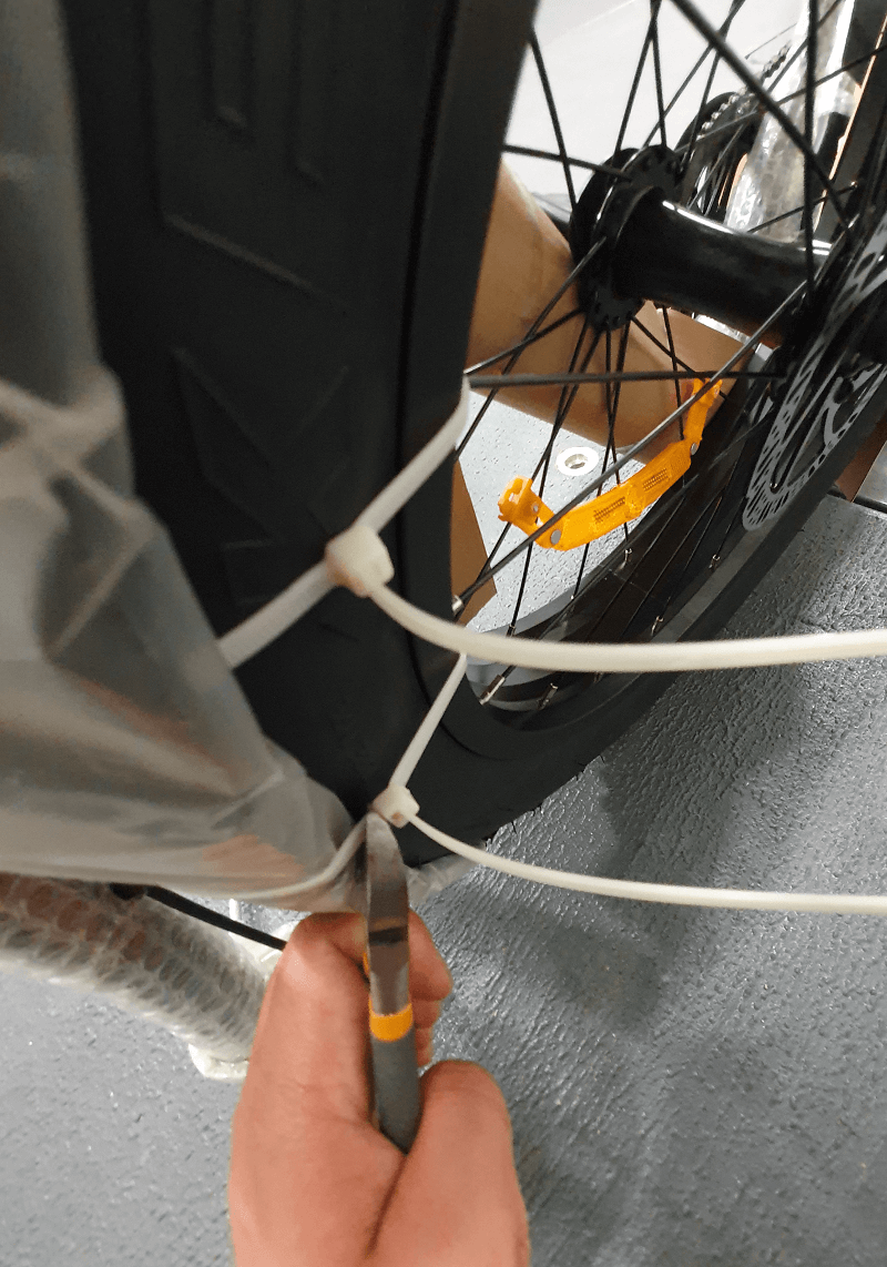
STEP 1
Remove all protective material from the bike
IMPORTANT: Please take care so that the bike frame does not get scratched.
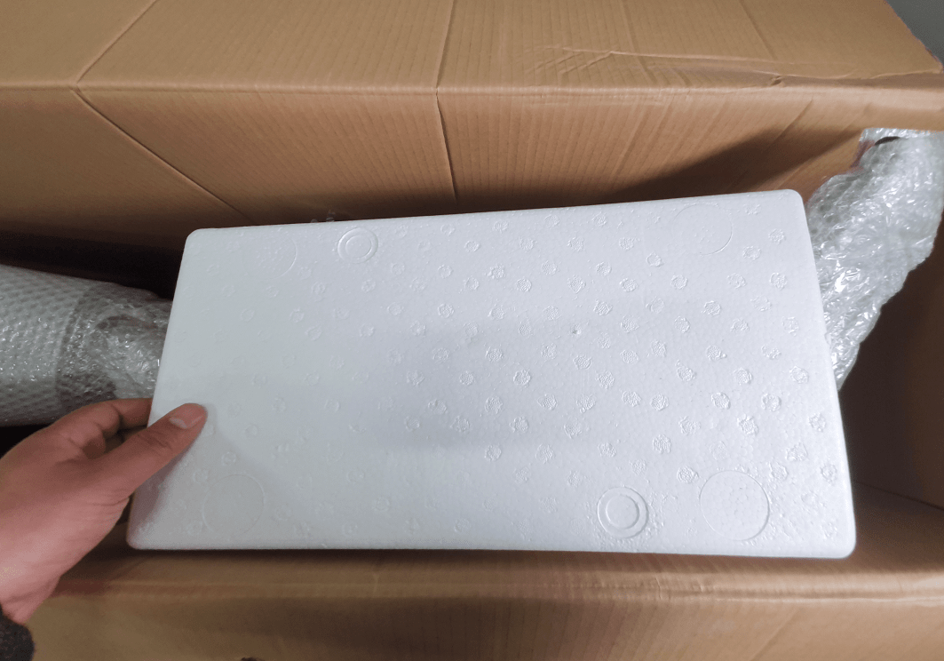
STEP 2
Open the accessories box, which includes the adapter, basic assembly tools, pedals, remaining footpeg, bike manual and LCD manual. Your bike should look the same as the photo below, flipped upside down on the large piece of white foam to use as a workmat.

CHAPTER 5: FRONT MUDGUARD ASSEMBLY
Install the front mudguard using the 2 bolts provided already in the fork center.

CHAPTER 6: FRONT WHEEL ASSEMBLY
STEP 1
Remove the 'Thru Axle' 6mm Allen Key.
-Optional: put blue loctite on Thru Axle threads for longer service life (red loctite is not recommended!)
Remove 1x plastic brake pad blocker from front brake.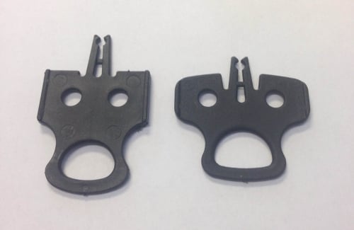
Care to line up the rotor disc into the brake caliper when placing the wheel into the fork.

Since the bike is upside down, this way will be easier to align everything.
Insert Thru Axle and push and wriggle it through to the other side of the wheel lining up the other suspension fork. The fork will move up and down so line it up carefully to insert the thru axle. Then secure with the axle cap nut. These do not need to be extremely tight as they are not the main securing factors. In fact for this fork design it is the 4x silver bolts adjacent, refer to next photo.

Tighten the Axle Cap first to medium tight (6nm), then the 4x silver bolts afterwards to medium~hard tight (9nm).
STEP 2
Firstly spin the front wheel. If there is brake noise for more than half of it's rotation, then refer to brake adjustment guide here. It will be covered again later in this guide.
Eg. Brake adjustment, photo provided does need adjustment. Yours may not. What we are looking for is the rotor disc to be clear in the center of the brake. Using the 5mm allen key from the tool kit, the bolt where the red arrow is, loosen, recenter and tighten again to medium~hard tight 9nm.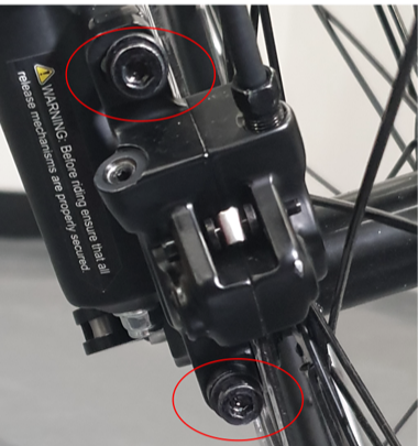
Now it is time to FLIP THE BIKE back to normal, prop the kickstand ready for this. Remove all foam packaging.
CHAPTER 7: HANDLEBARS, STEM & PEDALS ASSEMBLY
STEP 1
Correct the stem and handlebar position, see photos for guidance. Tool: 5mm allen key.


STEP 2
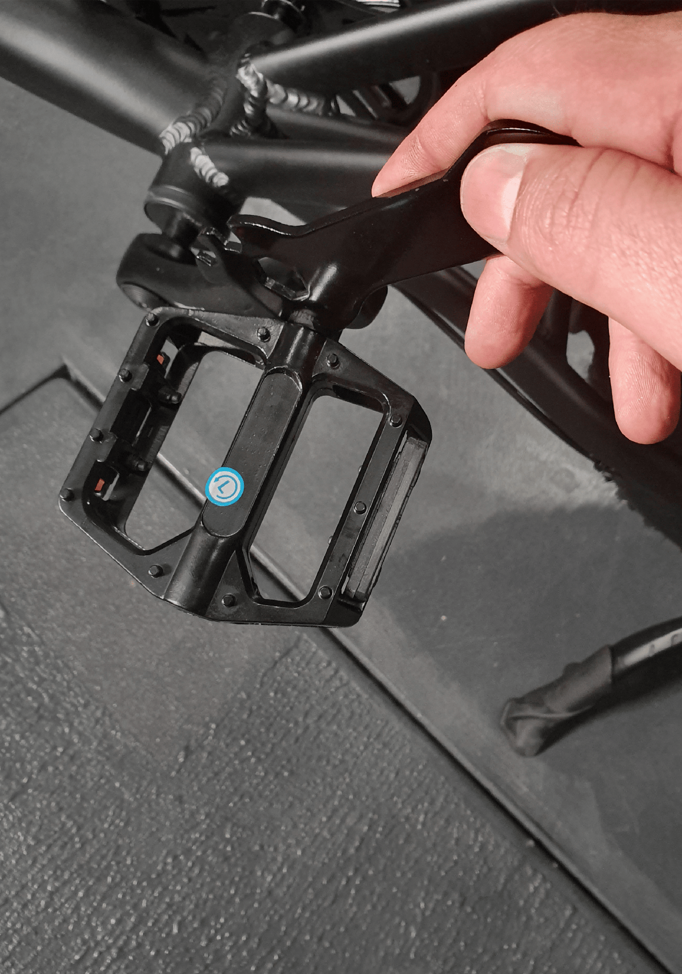
IMPORTANT: This step is sensitive and if done wrong, the threads on the pedal or the crank might get stripped. You should tighten the pedals by hand as much as possible and then fully tighten them by using a wrench.
IMPORTANT: Please ensure the pedals are fully tightened otherwise pedals can gradually get loosen and strip the crank arm threads.
RIGHT PEDAL - Thread is standard, right to tighten. LEFT PEDAL - Thread is reversed, left to tighten.
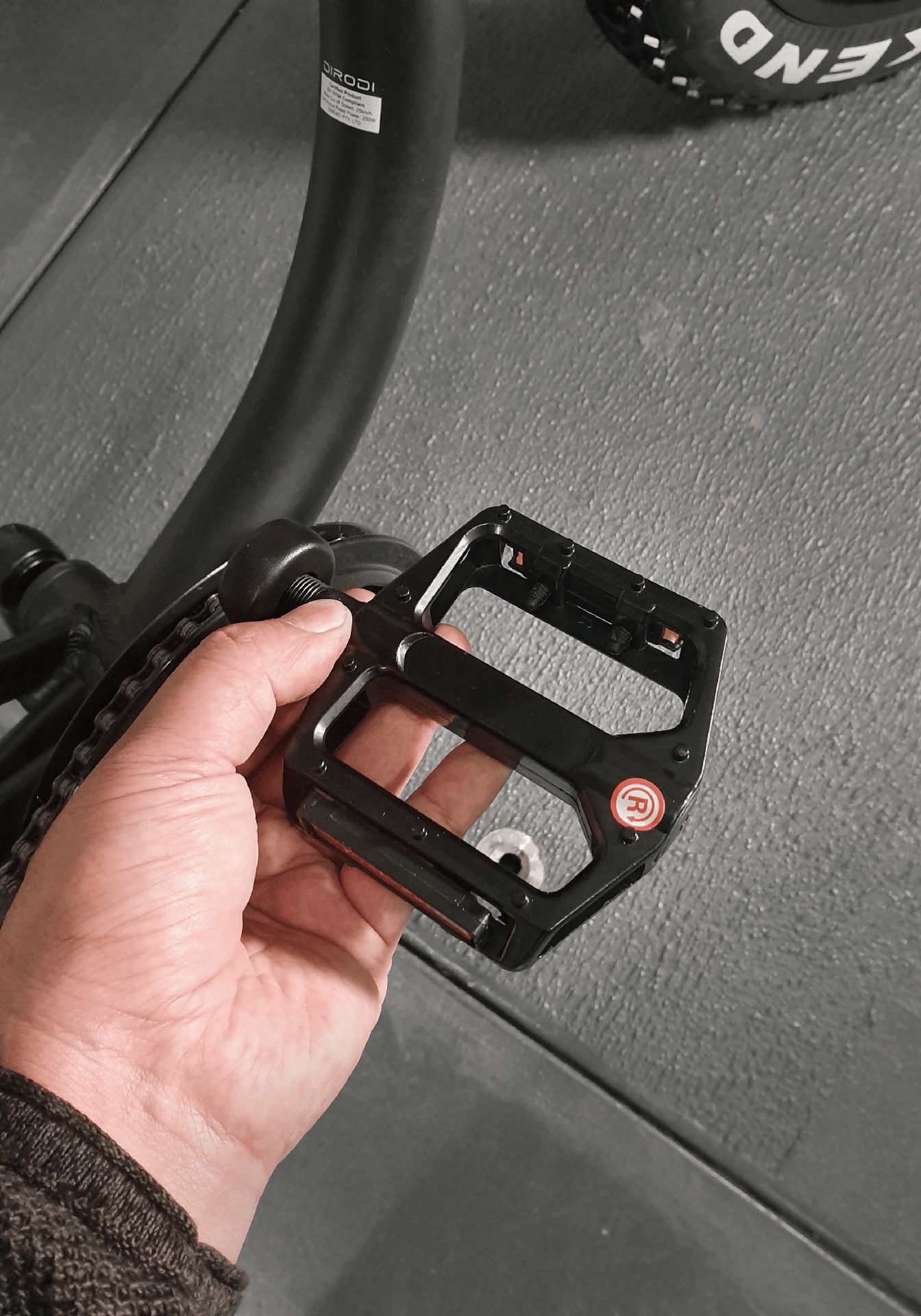
Tighten both pedals fully by using a wrench. Please ensure both pedals are fully tightened, medium~hard tight (14nm).
IMPORTANT: Ensure both pedals are fully tightened. If they are not installed correctly they will fall off and damage the crank thread which can be extremely dangerous while riding. This is something that is not covered under warranty so please take care.
CHAPTER 8: FOOTREST ASSEMBLY
STEP 1
For Rover5, only the brakeside footpeg, customer must install. Please remove the 2 bolts on brakeside footpeg mount with provided 6mm allen key. Line up the footpeg and install bolts. Start the bolt by hand to ensure it is going in straight and finish to tight with the tool.
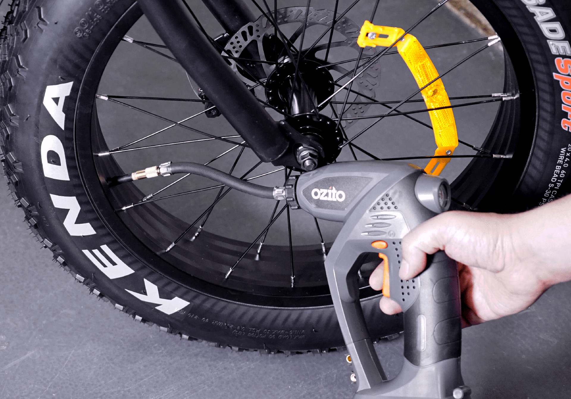
CHAPTER 9: PUMPING THE TYRES
STEP 1
Pump front and rear tyres to 30PSI (15-20PSI for beach/off road when needed)
CHAPTER 10: FINISHING TOUCHES
The bike is almost complete! Install the front light with wrench tool provided. You're welcome to use one of your own tools (13mm socket or wrench) as it will make the job easier.

DOT SAE -Writing here depicts orientation of light.


NOTE: ALL CABLE TO PASS THROUGH ON TOP OF THE HEADLIGHT MOUNT AS PICTURED.

We have provided extra photos for the headlight mounting process for your convenience.
Special note: Start the bolt by hand and finish with the tool to ensure the bolt is straight
Connect the light cable, following the arrow and notch in the green connector. Finish with the locking fastener.


Front Light Angle, perpenticular to ground or a few degrees downaward as per preference. However, do not angle the light up and use the light function to adjust for scenario for safety and respect of others.
eg. Highbeam for highways, lowbeam for streets and bike paths (bike paths when not passing pedestrians) and mini light (white) when passing pedestrians.
Did you know it is illegal to use fog light (yellow) when there is no fog? It applies to cars with fog lights as well. This is due to yellow lights being mistaken for indicators. Mistaken for indicator can be cause of accident. Same applies for indicator units made for ebikes, they have ot been made legal, due to vehicles anticipating indicator vehicles being capable of proper road speeds. Mirrors are legal to use. Trailers must have a flag.
Rover Standard Handlebars are already ready to go out of box, but check over all the handlebar accessories to fit the desired angle and tightness. For example, the bell, keypad and display will need a tighten with a 3mm allen key. Also the brake levers can be adjusted for hand size using a 2mm allen key, refer to photo (recommended screw in until screw is flush with lever).
Correct rubber stoppers, for steering protection against the frame paint.


Brakeside Footpeg: The brakeside footpeg does not come preinstalled, please undo the 2x bolts and install supplied footpeg from box. See below photo.
Note: Complimentary Rover rear basket, battery must be removed in order to install rear basket to frame. Insert all 4 bolts, some driving of the bolts may be required for them to sit flush. Proceed to tighten all bolts with nuts provided, 9nm~.
Rear Derailleur / GEARS
The rear derailleur has been adjusted at the factory, but due to parts movement during shipment, slight readjustments might be necessary. Derailleur adjustment is made by the barrel adjuster and “H” and “L” screws, as shown in the photos below.
The process is explained in detail in the video below:
https://www.youtube.com/watch?v=UkZxPIZ1ngY
NOTE: Please note that as the derailleur is already adjusted at the factory, any issues in changing gears between gears #2 to #6 should be easily solved by turning the barrel adjuster in the right direction (as per the instructions in the video above). After the gears are smoothly changed between gear #2 to #6, please test gear #1 (the largest cog) and #7 (the smallest cog). If you have any issues with gear #1, you need to adjust the “L” screw, and if you have any issues with gear #7, you need to adjust the “H” screw, as explained in the video above.
Battery & Lock/Key
The Gen5 battery has been upgraded to full alloy design and the slider is designed for a tight fit to ensure good contact for the electricty and security.
-Please refer to these photos to remember which way to lock the battery in case you thought the battery was locked but indeed wasn't and eventuated to the battery being stolen.
BATTERY: LEFT (CCW) = UNLOCK, (CW) RIGHT = LOCKED

Battery Level Indicator: Red - 0-30%, 1st Green 30-65%, 2nd Green 65-100%
Shown below is the battery hard on/off switch and the charging port.
Shown below is the main battery connection to the bike and fuse access. Fuse should be opened by a professional.
CHAPTER 11: DISK BRAKE ADJUSTMENT
NEED FURTHER BRAKE ADJUSTMENT HELP?
EXTERNAL GUIDES ON BRAKES
https://www.youtube.com/watch?v=uk_nC9anQcM
CHAPTER 12: REAR DERAILLEUR ADJUSTMENT
NEED GEAR ADJUSTMENT HELP?
The rear derailleur has been adjusted in the factory but due to parts movement during shipment, slight re-adjustments might be necessary. Derailleur adjustment is done by barrel adjuster and “H” and “L” screws as shown in photos below.
The process is explained in the video below in detail:
https://www.youtube.com/watch?v=UkZxPIZ1ngY
CHAPTER 13: OPERATING THE BIKE
IMPORTANT: The laws around the use of electric bikes on public lands, roads and areas vary from state to state. We recommend you always check your local council and road traffic laws prior to using a bike to ensure you are aware of any restrictions that may affect the use of motorised vehicles. Always use appropriate protective riding equipment such as an approved helmet and suitable clothing.
TURNING ON AND RIDING THE BIKE
Battery inserted, battery button switched on. Press and hold the power button on keypad until the bike’s LCD turns on (photo 1). Then by pressing the ‘+’ button, you can increase the pedal assist level from 1 to 6. What is Pedal Assist (PAS)?
PAS is the pedal electric power.
-PAS 1 being max 15km/h~ with a slow gradient to climb to that speed.
-PAS 6 being the max speed eg. 25km/h with a fast gradient to rapidly climb to that speed.
Depending on which PAS mode you use will determine how far you can travel on one charge.
Other factors of battery performance is if you have unlocked the speed, wattage and throttle for off-road use and 2 person riding, along with other factors like terrain, incline, carry load and pedal power determine how far you can ride on a single charge.
After setting the pedal assist level, you can start riding the bike. It is suggested to always start your ride at pedal assist level 1 and then gradually increase it, if needed.
Rover Gen5 Controls

Rover Gen6 Controls
CHARGER
How to operate charger - Green = battery full or disconnected. Red = still charging


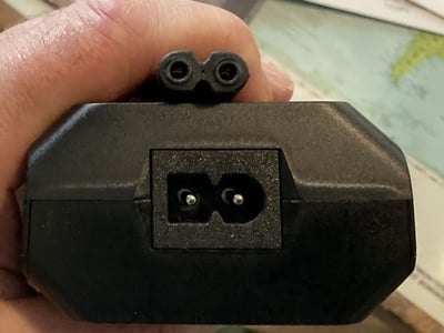
These are the normal C7(P)/C8(P) variety of plug (C7) and socket (C8) which has two forms. A polarized version for certain global markets where Active and Neutral requires specific connections, and a non polarized for areas that do not. The charger is fitted with a generic polarized socket (C8P). The socket is designed in such a way that both polarized and non polarized plugs can be used safely.
The cord supplied is non polarized, this as because Australia runs AC mains power and our standards do not require specific polarisation and it doesn't matter which way the plug is inserted. What you have is correct.
Simply plug in and then plug your charger into the wall, then into your battery.
BATTERY
DiroDi Rover Gen5 Battery brand is from Joycube. The cells are from Samsung.
For battery care and charging tips, we can make some recommendations to maintain the battery performance over time.
-Do not drain battery to off often when riding the ebike.
-Charge for the amount of time that the battery needs for safety. Max charge time 10 hours (0%-100%).
-When charging the battery with battery still inserted in bike, please switch battery to off with red switch.
-After using the ebike heavily and the battery is very warm, wait for battery to cool before charging to prolong cell health.
-When ebike is not in use, but battery is still inserted in the ebike - please switch battery off at red switch.
MECHANICAL MAINTENANCE TIPS
This manual is designed for direct to consumer purchases of DiroDi eBikes. Therefore it is recommended to learn general maintenance tips to keep a high quality riding experience and could perhaps save you money years down the track.
-The chain is galvanized and therefore is highly resistant to rust, perfect for Rovers, furthermore the motor is hub driven so chain wear is also minimized compared to a mid-drive system.
-In saying this, not all components can be galvanized. So keep in mind if you live near the beach with salty air, park outdoors or ride on the beach often without cleaning your bike. Expect surface rust on the gear cassette and bearings to degrade.
-To prevent this, chain lube (eg. touring / all-road) it will extend to provide minor protection to the gear cassette.
-Cleaning recommendations: Bike or Car wash is suitable, using brush or cloth but avoid pressure & hosing the motor and avoid washing any electrical component. Just use the damp cloth or dry brush for sand. You can use compressed air for hard to reach places or a professional clean, but spin the wheel a few times to shake off excess water before compressed air.
-Lube chain after clean, wipe off excess.
-Check tyre pressure every month. Road 30PSI, Off-road 20PSI, Beach 15PSI.
-When transporting the bike on its side or laying flat for any reason, choose to lay it on the brake side (to protect the gear derailleur - cage is included for further protection).
-Brake pads installed on our Tektro system are the Green Organic compound. These are a good choice for a quiet 'corky' feel, medium lifespan and medium braking power in wet conditions. Lifespan 6-12 months depending on braking style. For braking advice, using a pulse technique and always using both brakes in a feathered manner (no need to hard brake in all circumstances)- no need to over hard press the brake or favour one brake which puts strain on the pads or would need replacement before the other side.
-Metal 'Sintered' pads offer better in wet conditions braking power, but are louder and wear the rotor faster. Rotor lifespan 1-5 years.
-Rotor noise, slapping the brake pads? Some brake caliper adjustment may be needed, but most often it is because the rider needed to hard brake, creating heat to warp the rotor or was riding in wet conditions and braking surface was affected. To fix this, simply wait for dry conditions and ride fast enough to long pulse and feather (or like skipping a stone on a lake) to create a renewed braking surface on the rotor with consistant and pulsed contact. Noise can come back and forth from heat and braking intensity. Brakes will correct themselves.
-However do check pad life left, by looking into the caliper from above. Thickness of compound atleast 1mm or more.
-Check the wheel nuts every 3 months. Especially for the front wheel. Rover Plus has 6 bolts to tighten whereas Rover Standard has only 2 wheel nuts.
-1000w expectations / limits. The max current for the controller is 30A, which is a very high rating and can be measured on screen with the 'Watt' inidactor on the right side of the display. Treat it like a 'Tachometer'. For example if you are riding the bike fully off-road mode with throttle unlocked, riding with 2 persons and riding uphill with no pedalling the eBike may need some assistance. Depending of variables such as incline or weight or battery percentage remaining. Please pedal your bike as necessary and listen to your motor.
-250w max current is 17A, this model can still do everything the listed above just with less power. Adequate for daily use and assistance with pedalling as per ebike laws.

___________________________________________________________________________________________________________________________________________
THROTTLE
Please note the bike’s throttle max speed has been limited to 6km/h to be compliant with Australian standards. However, you can unlock the limit only if you intend to use the bike for off-road use only by the following steps:
-Bike off, battery switch still on
-Hold down both brakes and throttle
-While using left thumb to switch the bike on/off 3 times (on long press, off long press)
-After 3rd off, release the brakes/throttle and turn bike back on
-Test Throttle: Lean bike back on kickstand, push grey 'throttle toggle on' button IN to activate throttle 'always on' mode (toggle button out to have throttle OFF/ cruise control mode)
NOTE: Unlocking the throttle will put additional strain on the motor if used as the primary source of propulsion. This needs to be taken into consideration and used with care so as not to damage the electrical components from overuse. Additional care should be taken if using the 250W model.
WALK ASSIST FEATURE
This feature is designed to allow the motor to push the bike along while you walk beside it, up a parking ramp for example. In order to activate the walk-assist feature, please turn on the bike and press and hold the “-” (MINUS) button.
Passcode Instructions
Turn on the bike.
Press and hold the '+' and 'SET' buttons for 5 seconds until the light turns on.
Press and hold the plus and minus buttons until the display changes
Input your password by changing the digits with '+' and '-', use 'SET' to jump to the next digit.
Hold 'SET' to save
*Now the bike password is activated and will need to be input every time you turn the bike on*
To change the password turn on the bike, hold down the 'SET' and '-' buttons, input the original password then input the new password, hold 'SET' to save
To deactivate the password feature press and hold the '+' and 'SET' buttons for five seconds while the bike is on and unlocked
If you want a passcode and throttle unlock, best to proceed with the throttle unlock first.
IMPORTANT NOTE REGARDING YOUR BIKE SECURITY
Before using the bike, please record the bike's serial number in case your bike gets stolen. We don't keep track of each bike's serial number for each order. You will need your bike's serial number to lodge a police report if it is stolen.
We strongly recommend using a premium lock to secure the bike. We suggest using ABUS or Kryptonite U locks. We suggest investing around 5% of the bike's price to buy a lock.
In addition to using a U lock, the following methods can be used to further reduce the risk of theft:
- Using a quality bike lock - Check our website for our range of locks
- Installing a gps and/or alarm. We recommend KNOG SCOUT GPS w/ ALARM or Apple Airtag / TILE at the minimum for tracking your ebike.
- Insuring your e-bike. By doing a google search, you can find companies that offer e-bike insurance in Australia.
In our experience, bike parts theft (e.g. saddle, tyres, LCD, etc.) happens very rarely as these parts are not usually compatible with other brand bikes and therefore do not have a reselling value. Therefore, it's better to keep your focus on securing the bike frame rather than on different parts.
Unfortunately, electric bike theft is common in Australia. Even by using the best lock and security systems, your bike is not going to become 100% theft-proof. Therefore, it's always better to avoid parking your bike in public places for an extended period of time or overnight.
BIKE SERIAL NUMBER
Please record the serial number of your bike in the case of theft.
For Dirodi Rover models, it is located on the head tube as well as sticker on frame starting with PSG...
They are designed to be used as the owner's reference in the event of theft to provide identification to police.